


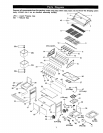
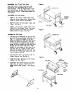
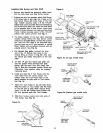
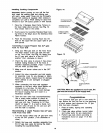
Installing Side Burner and Side Shelf Figure 9
1. Remove and discard the protective rubber boots
from the Side Shelf and Side Bumer braces.
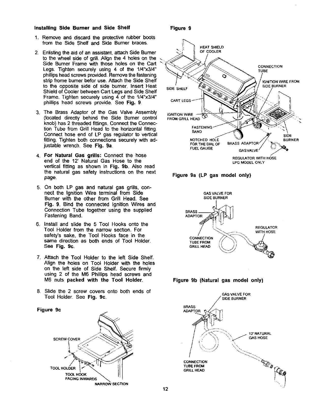
2. Enlisting the aid of an assistant, attach Side Bumer
to the wheel side of gdll. Align the 4 holes on the
Side Burner Frame with those holes on the Cart
Legs. Tighten securely using 4 of the 1/4"x3/4"
phillips head screws provided. Remove the fastening
strip frome bumer befor use. Attach the Side Shelf
to the opposite side of side burner. Insert Heat
Shield of Cooler between Cart Legs and Side Shelf
Frame. Tighten securely using 4 of the 1/4"x3/4"
phillips head screws provide. See Fig. 9.
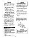
3. The Brass Adaptor of the Gas Valve Assembly
(located directly behind the Side Burner control
knob) has 2 threaded fittings. Connect the Connec-
tion Tube from Grill Head to the horizontal fitting.
Connect hose end of LP gas regulator to vertical
fitting. Tighten both connections securely with ad-
justable wrench. See Fig. 9a.
4. For Natural Gas grills: Connect the hose
end of the 12' Natural Gas Hose to the
vertical fitting as shown in Fig. 9b. Also read
the natural gas safety instructions on the next
page.
5. On both LP gas and natural gas grills, con-
nect the Ignition Wire terminal from Side
Burner with the other from Grill Head. See
Fig. 9. Bind the connected Ignition Wires and
Connection Tube together using the supplied
Fastening Band.
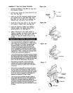
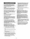
6. Install and slide the 5 Tool Hooks onto the
Tool Holder from the narrow section. For
safety's sake, the Tool Hooks face in the
same direction as both ends of Tool Holder.
See Fig. 9c.
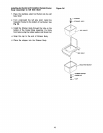
HEAT SHIELD
OF COOLER
SIDE SHELF
!
CAR'
CONNECTION
TUBE
SIDEBURNER
FROM
IGNITION WIRE
FROM GRILL HEAD
BAND
NOTCHED HOLE
FORTHE D_LOF
FUELGAUGE
" SIDE
BURNER
BRASS ADAPTOR , _\_
GASVALVE _
REGULATOR WITH HOSE
LFG MODEL ONLY
Figure 9a (LP gas model only)
GAS VALVE FOR
SIDE BURNER
ADAPTOR
CONNECTION
TUBE FROM
GRILL HEAD
REGULATOR
WITH HOSE
7. Attach the Tool Holder to the left Side Shelf.
Align the holes on Tool Holder with the holes
on the left side of Side Shelf. Secure firmly
using 2 of the M6 Phillips head screws and
M6 nuts packed with the Tool Holder,
Figure 9b (Natural gas model only)
8. Slide the 2 screw covers onto both ends of
Tool Holder. See Fig. 9c.
Figure 9c
SCREW COVER
TOOL HOLDER
TOOL HOOK
FACING INWARDS
NARROW SECTION
12
GAS VALVE FOR
,IDE BURNER
BRASS
ADAPTOR ,
"" T
/ //_\ 12'NA URAL
/ _ _ ",\J GASHOBE
CONNECTION " _ "
TUBE FROM
GRILL HEAD