


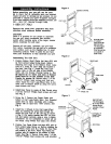
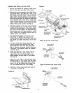
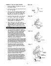
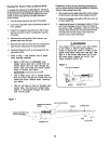
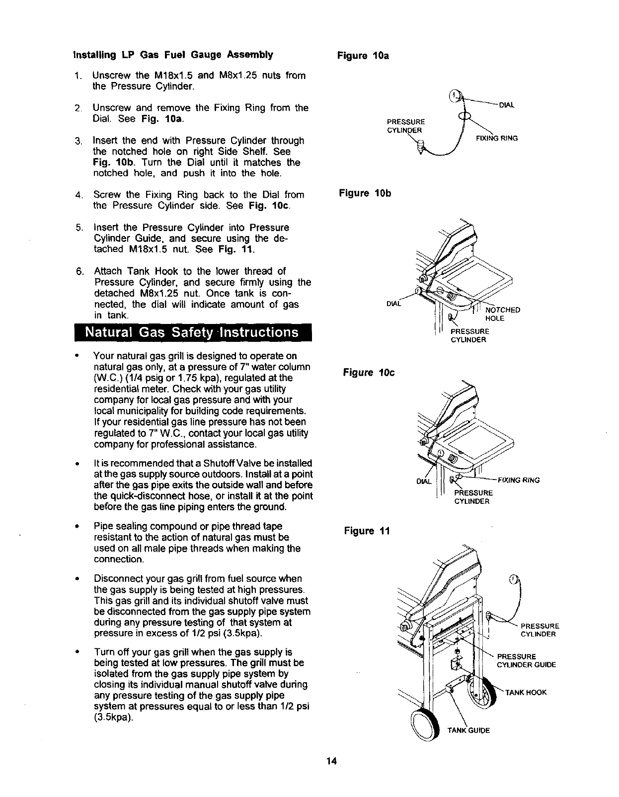
Installing LP Gas Fuel Gauge Assembly
1. Unscrew the M18xl.5 and M8x1.25 nuts from
the Pressure Cylinder.
Figure 10a
2.
3.
Unscrew and remove the Fixing Ring from the
Dial. See Fig. 10a.
Insert the end with Pressure Cylinder through
the notched hole on right Side Shelf. See
Fig. 10b. Turn the Dial until it matches the
notched hole, and push it into the hole.
PRESSURE
CYLtNDER
FIXING RING
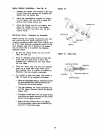
4. Screw the Fixing Ring back to the Dial from
the Pressure Cylinder side. See Fig. 10c.
Figure lob
5. Insert the Pressure Cylinder into Pressure
Cylinder Guide, and secure using the de-
tached M18xl.5 nut. See Fig. 11.
6. Attach Tank Hook to the lower thread of
Pressure Cylinder, and secure firmly using the
detached M8xl.25 nut. Once tank is con-
nected, the dial will indicate amount of gas
in tank.
Your natural gas gdll is designed to operate on
natural gas only, at a pressure of 7" water column
(W.C.) (1/4 psig or 1.75 kpa), regulated atthe
residential meter. Check with your gas utility
company for local gas pressure and with your
local municipality for building code requirements.
If your residential gas line pressure has not been
regulated to 7" W.C., contact your local gas utility
company for professional assistance.
It is recommended that a Shutoff Valve be installed
at the gas supply source outdoors. Install at a point
after the gas pipe exits the outside wall and before
the quick-disconnect hose, or inst_ll it at the point
before the gas line piping enters the ground.
Pipe sealing compound or pipe thread tape
resistant to the action of natural gas must be
used on all male pipe threads when making the
connection.
Disconnect your gas grill from fuel source when
the gas supply is being tested at high pressures.
This gas grill and its individual shutoff valve must
be disconnected from the gas supply pipe system
dudng any pressure testing of that system at
pressure in excess of 1/2 psi (3.5kpa).
Turn off your gas grill when the gas supply is
being tested at low pressures. The grill must be
isolated from the gas supply pipe system by
closing its individual manual shutoff valve dudng
any pressure testing of the gas supply pipe
system at pressures equal to or less than 1/2 psi
(3.5kpa),
D_L
Figure 10c
DIAL
Figure 11
NOTCHED
HOLE
PRESSURE
CYLINDER
FIXING RING
PRESSURE
CYLINDER
_PRESSURE
TANK GUIDE
14