104
Additional information
XV-D705GD/XV-D703TN
LET0142-003A
[2U, 3U, 4U, US, UB, UT] EN
AV COMPU LINK remote control system
Connection and Setup
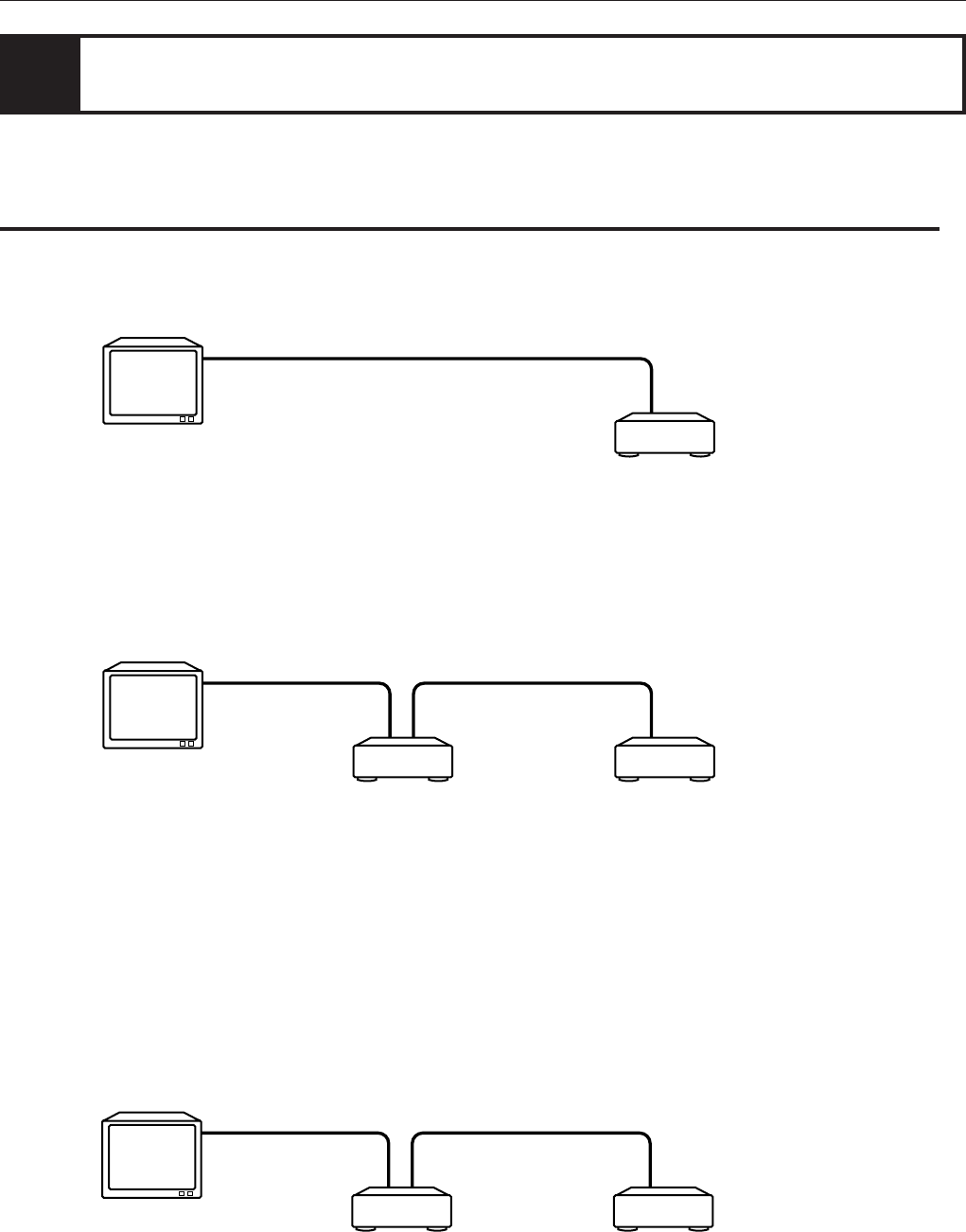
• Using the AV COMPU LINK cable, connect the AV COMPU LINK terminals of each component to one another.
When you buy a separate TV, VCR, DVD player, receiver, or other components and connect them to each other, you
have to operate each component individually. JVC’s AV COMPU LINK remote control system meets the demand
for a system made up of single components and has the ease of operation of a single unit.
• If you connect a DVD player with a television via AV COMPU LINK, set the DVD player’s AV COMPU LINK setting as
follows.
• When connecting with VIDEO-1 input terminal of the television: DVD2
• When connecting with VIDEO-2 input terminal of the television: DVD3
• If you connect a DVD player with a television and VCR via AV COMPU LINK, set the VCR’s Remote Control Code and
DVD player’s AV COMPU LINK setting as follows.
• When connecting with VIDEO-1 input terminal of the television:
DVD player’s AV COMPU LINK setting: DVD2
VCR’s Remote Control Code: B
• When connecting with VIDEO-2 input terminal of the television:
DVD player’s AV COMPU LINK setting: DVD3
VCR’s Remote Control Code: A
• If you connect a DVD player with a television and receiver via AV COMPU LINK, set the DVD player’s AV
COMPU LINK setting to DVD1.
• The DVD player’s AV COMPU LINK setting is operated in the “PREFERENCE” display. See page 57 for
operation.
• About the connection between the TV and the Receiver, refer to Receiver’s Instructions.
Receiver DVD player
TV
DVD player
TV
To AV COMPU LINK
DVD player VCR (Video Cassette Recorder)
TV
To AV COMPU LINK
To AV COMPU LINK


