


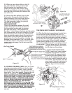
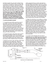
HOSE CLAMPS FROM MAZDA ARE BEST
REMOVED BY APPROACHING FROM THE
SIDE WITH NEEDLE NOSE PLIERS. GRASP
ALL THREE TANGS AT ONCE AND COMPRESS
THEM TOGETHER. THIS IS EASIER TO DO
WITH THE THROTTLE BODY ALREADY LOOSE
FROM THE INTAKE MANIFOLD. Plug the
coolant hoses with a screwdriver, golf tee, or pen-
cil to prevent the leakage of coolant (OR - keep
the hose ends above the radiator cap level to pre-
vent leakage). Release the throttle cable from the
throttle shaft spool. Release the Throttle Position
Switch harness by lifting the small wire clip that
runs around the rectangular base of the connec-
tor. If the throttle body gasket tears as you
remove it (even though it is made of metal, it can
tear), you will need to clean off the old gasket
from both surfaces, the throttle body and the
intake manifold. Carefully use a knife or the back-
side of a hacksaw blade to scrape the mounting
surfaces clean. DO NOT SCRATCH OR MAR
THE MOUNTING SURFACES IN ANY WAY.
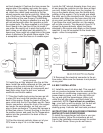
Immediately below and behind the throttle body
on the intake manifold is a steel support brace in
the shape of an inverted “L” attached by four
12mm headed dolts. Remove the brace and re-
secure the wiring harness ground wire attached
at that point with one of the 12mm headed bolts.
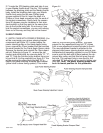
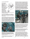
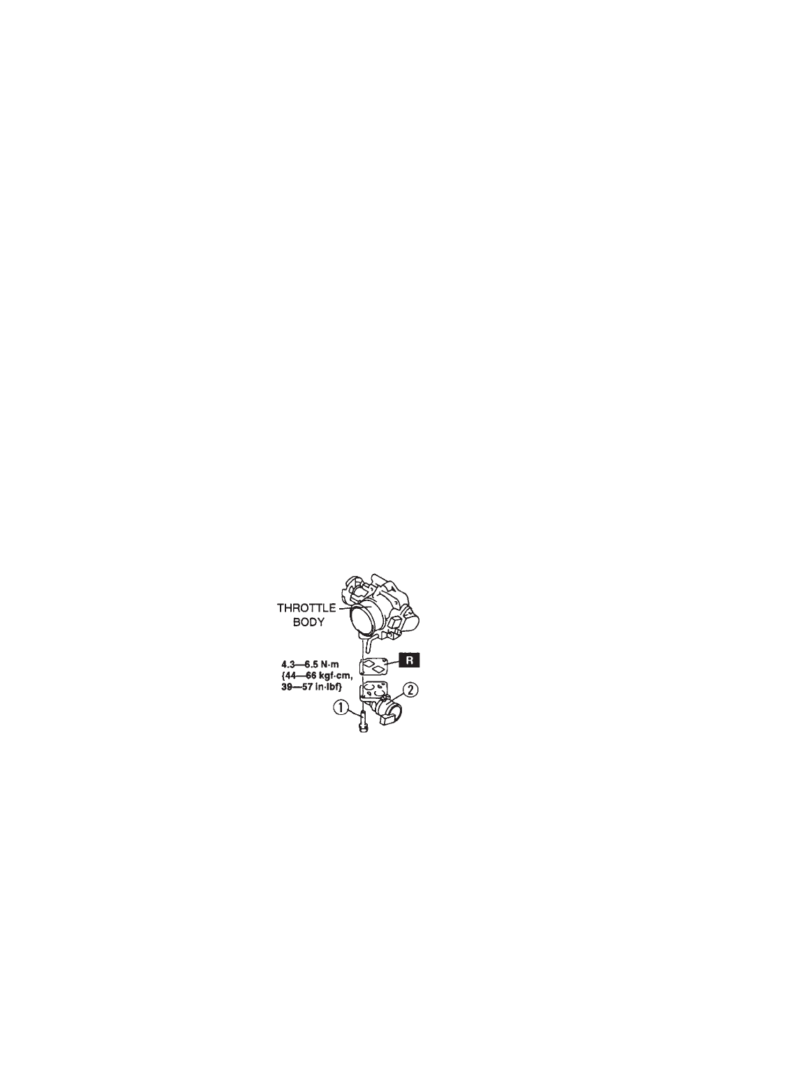
2.2 Moving to a worktable, remove the idle air
control (ICS) valve from the bottom of the throttle
body by removing the two
Phillips head screws. Use a
good quality screwdriver and
be careful not to strip the
Phillips head screw. If you
cannot loosen a screw with
the screwdriver, use a small
set of pliers from the side.
Carefully separate the two
units making sure not to tear
the gasket. The gasket will want to stay with the
Mazda ICS valve.
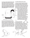
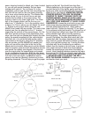
2.3 Take the Dummy Throttle body from your
supercharger kit and install the Mazda Idle Air
Control Valve (ICS) from step 2.2 on the bottom,
rotating the ICS valve 180 degrees so that the
electrical connector now points to the rear of the
engine. Use the Mazda original ICS to Throttle
body gasket.
2.4 Install the Dummy Throttle Body and ICS
valve assembly back onto the intake manifold in
the same position as the standard Mazda throttle
body. Use the original gasket or the1104 adhesive
on the mating surfaces and the two new 8mm x
40mm long bolts provided in the lower two holes
on the dummy throttle body. Reconnect the
coolant hoses to the brass coolant barbs on the
front and side of the dummy throttle body.
2.5 Do not connect the ICS electrical connection
until after the next step.
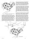
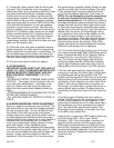
2.6 Wiring Harness Modifications:
Locate the main engine wiring harness on the left
side of the engine (as viewed from the front of the
engine) where it runs between the intake manifold
and cam cover. Cut the strap of the white plastic
harness anchor at the front and release the fire-
wall end of the harness by gently prying the
release tab on the securing clamp located near
the rear engine lifting eye. Starting at the forward
point where the four black/yellow wires come out
of the harness, cut the black tape binding the
plastic corrugated tubing so that you can access
the wires within. Locate the wiring branch of the
ICS valve connector and follow the wires to the
main harness. Pull these two wires (purple and
orange) back free from the main harness about 4-
5 inches so that you have enough slack to plug
the connector in the repositioned ICS valve. Cut a
length of the small diameter corrugated tubing
supplied in the kit to cover the wires on the ICS
branch from the plug to the main harness with an
additional inch of tubing to protrude into the main
harness tubing. Locate the wiring harness branch
for the Throttle Position Switch (TPS) that origi-
nally connected at the throttle body connector.
Pull these wires back to about 4 inches from the
firewall. If the construction of your particular har-
ness is such that you cannot free all three wires
(light green/red, green/black and black/pink) all
the way back, cut the offending wire (usually light
green/red) and pull the wires with the connector
back free. Then strip about 1/4 inch of insulation
of each end of the cut wire and using the Crimp
connector supplied; insert a stripped end into
each end of the connector. Crimp (collapse) each
end of the connector onto stripped ends, making
sure that the connection is secure. With the crimp
connector installed on the wire, shrink seal the
ends of the Crimp connector by heating it with a
heat gun or a hair blow dryer. Using some of the
small diameter corrugated tubing provided, cover
the TPS harness branch. Wrap the main harness
and branches with the roll of tape supplied in the
kit, in the same manner as the factory had.
Reattach the harness at the rear harness clamp
by snapping it back in place and at the front by
using a new Ty-Wrap strap through the base of
the white plastic anchor. You can now plug in the
ICS valve connector by routing the harness
branch under and around the intake manifold to
the ICS valve. The TPS connector will be plugged
in after installation of the supercharger and throt-
tle body assembly.
3
1/07999-200