


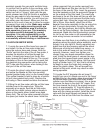
not back towards it. Continue the hose across the
engine side of the radiator and under the upper
radiator hose. Using the Ty-Wrapp straps provid-
ed, attach the rubber hose securely to the fan
shroud supports near the fan motor(s). Attach the
end of the hose to the Brass Elbow fitting attached
to the bottom of the new Dummy Throttle Body.
Make sure that the hose is attached in a way that
will not interfere with either fan operation or with
the engine belts. The hose supplied is a bit longer
than it needs to be, feel free to trim its length if
you prefer. Be careful not to pinch the hose at any
point, doing so will affect your idle stability. On
some cars, there might be a slight kink in the hose
where it attaches to the plastic elbow nipple. This
is acceptable, orient the hose so it remains open.
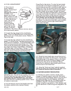
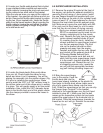
7.6 Install the air filter element over the air filter
base. Install the waffle patterned air filter cap and
secure using the nuts provided. Use the Ty-
Wrapps provided to secure all components and
keep them clear from the belt runs, exhaust
manifolds and throttle cables.
7.7 Take the throttle body wiring harness as left
in step #2.6 and route the harness along the
back of the engine. Route the branch of the har-
ness, which has the Air Flow Meter and Air Temp
Sensor connectors, along the front of the engine
and under the supercharger, so that you can
plug in these connectors. Tie-wrap the harness in
at least two places. Connect the plug to the throt-
tle position sensor and push the Air Temperature
sensor into the grommet in the back of the air
cleaner base.
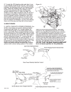
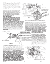
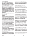
7.8 Find the internal restrictor taken out of your
PCV hose in step #1.4 or in the hose bag.
Locate the 3/8” internal diameter hose from your
kit and press the restrictor into this hose at least
one inch. Attach this hose from the ‘medium’ fit-
ting on the plastic elbow (near the throttle body,
pointing to the engine). Cut to length and attach
the other end to the camshaft cover fitting on the
exhaust side. Make sure the hose does not kink
at any point and that the restrictor is not left out.
If you leave the small restrictor out, the engine
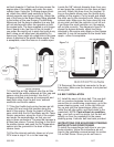
will not idle correctly. The diagram in figure #7.5
shows the bypass actuator signal line being
attached to the engine side nipple on the bypass
manifold. It may be connected to the fender side
nipple - either is acceptable.
7.9 Reconnect the electrical connector to the air
flow meter. Make sure the harness is not pinched
at any point.
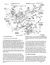
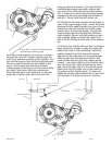
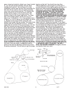
8.0 BELT INSTALLATION
8.1 Install the new 4-rib drive belt. This new belt
will run counter-clockwise from the crankshaft,
around the air conditioning compressor, up to the
power steering pump, over to the right idler pul-
ley, up and over the supercharger pulley, just
under the left idler pulley, and back down to the
crankshaft. NOTE: Cars without air condition-
ing - your belt run will be similar, but the belt will
simply run from the crankshaft to the power
steering pump. A shorter belt has been provided.
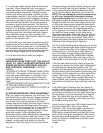
INSTRUCTIONS FOR NON-POWER STEERING
MIATAS WITH AIR CONDITIONING
To install the supercharger belt drive in your par-
ticular situation, follow the instructions as out-
lined in the installation manual except for section
3.0 on Belt Drives. Since you do not have a
10
1/07999-200
Figure 7.5
Figure 7.6