


3434
TRANSAXLE/MOTOR/BRAKEPROCEDURE 6
T
R
A
N
S
A
X
L
E
/
M
O
T
O
R
/
B
R
A
K
E
CAUTION
DO NOT overtighten the two (2) screws secur-
ing the bracket and rubber spacer to the rear
frame assembly. Otherwise, damage to the
bracket and rubber spacer may occur.
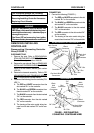
3. Secure the bracket and the rubber spacer to the
rear frame assembly using the two (2) screws
and self-locking nuts. Torque the two (2) self lock-
ing nuts between 16 - 20 in./lbs.
4. Align the mounting holes of the U - brace with the
mounting holes in the rear frame assembly.
5. Position the rubber spacer between the U - brace
and the rear frame assembly.
CAUTION
DO NOT overtighten the two (2) bolts securing
the U - brace and rubber spacer to the rear
frame assembly. Otherwise, damage to the
U - brace and rubber spacer may occur.
6. Secure the U - brace and the rubber spacer to
the rear frame assembly using the two (2) bolts,
spring washers, self-locking nuts, and four (4)
washers. Torque the two (2) self locking nuts
between 16 - 20 in./lbs.
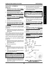
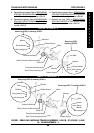
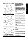
7. Rotate the top of the two (2) rear shock assem-
blies toward the frame.
8. Align the two (2) rear shock assemblies with the
two (2) mounting holes on the rear frame assem-
bly (DETAIL “A”).
9. Secure the two (2) rear shock assemblies to the
rear frame assembly using the existing screws
(DETAIL “A”). Securely tighten.
10. Connect the WHITE connector of the transaxle
assembly to the WHITE connector of the control
assembly.
11. Reinstall the disc brake assembly. Refer to
RE-
PLACING DISC BRAKE ASSEMBLY in PRO-
CEDURE 11 of this manual.
12. Reinstall the rear wheels. Refer to
REMOVING/IN-
STALLING THE REAR WHEELS in PROCEDURE
9 of the Owner’s Manual, part number 1090132.
13. Reinstall the batteries. Refer to
REMOVING/IN-
STALLING THE BATTERIES WITH CABLES in
PROCEDURE 4 of the Owners Manual, part
number 1090132.
14. Reinstall the rear shroud. Refer to
REMOVING/
INSTALLING THE REAR SHROUD in PROCE-
DURE 9 of the Owner’s Manual, part number
1090132.
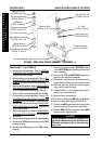
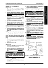
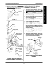
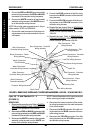
Panther MX - 4 (FIGURE 2)
REMOVING.
1. Remove the seat. Refer to REMOVING/IN-
STALLING THE SEAT in PROCEDURE 5 of the
Owner’s Manual, part number 1090132.
2. Remove the rear shroud. Refer to
REMOVING/
INSTALLING THE REAR SHROUD in PROCE-
DURE 9 of the Owner’s Manual, part number
1090132.
3. Remove the batteries. Refer to
REMOVING/IN-
STALLING THE BATTERIES WITH CABLE
ASSEMBLY in PROCEDURE 4 of the Owners
Manual, part number 1090132
4. Remove the rear wheels. Refer to
REMOVING/IN-
STALLING THE REAR WHEELS in PROCE-
DURE 9 of the Owner’s Manual, part number
1090132.
5. Remove the disc brake assembly. Refer to
RE-
PLACING DISC BRAKE ASSEMBLY in PRO-
CEDURE 11 of this Manual.
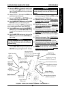
6. Remove the TOP bolts on the two (2) rear shock
absorbers (DETAIL “A”).
7. Rotate the top of the two (2) rear shock absorb-
ers away from the frame (DETAIL “A”).
8. Disconnect the WHITE connectors of the
transaxle assembly from the WHITE connectors
of the control assembly.
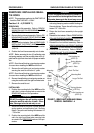
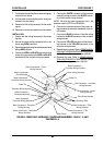
9. Remove the two (2) bolts, spring washers, self-
locking nuts, and four (4) washers securing the
U-brace and rubber spacer to the rear frame as-
sembly.
10. Remove the U-brace and rubber spacer from the
rear frame assembly.
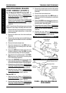
11. Remove the two (2) screws and self-locking nuts
securing the bracket and rubber spacer to the rear
frame assembly.
12. Remove the bracket and rubber spacer from the
rear frame assembly.
13. Slide the transaxle assembly out of the rear frame
assembly.
INSTALLING.
1. Slide the transaxle assembly into the rear frame
assembly.
2. Align the mounting holes in the bracket and the
rubber spacer with the mounting holes in the rear
frame assembly.