


3636
PROCEDURE 6
T
R
A
N
S
A
X
L
E
/
M
O
T
O
R
/
B
R
A
K
E
TRANSAXLE/MOTOR/BRAKE
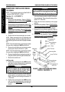
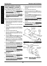
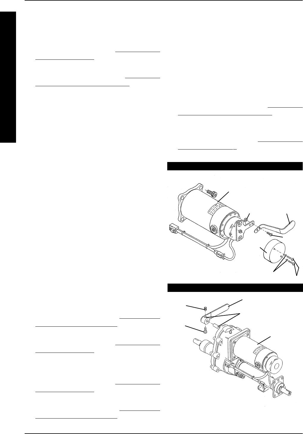
REPLACING BRAKE RELEASE
LEVER ASSEMBLY (FIGURE 4)
For All Models EXCEPT Panther MX - 4
1. Remove the seat. Refer to REMOVING/IN-
STALLING THE SEAT in PROCEDURE 5 of the
Owner’s Manual, part number 1090132.
2. Remove the rear shroud. Refer to
REMOVING/
INSTALLING THE REAR SHROUD in PROCE-
DURE 9 of the Owner’s Manual, part number
1090132.
NOTE: Save the two (2) mounting screws and spring
washers for reuse when reinstalling the brake cover.
3. Remove the two (2) mounting screws and spring
washers securing the brake cover to the motor/
brake assembly.
4. Remove the brake cover from the motor/brake
assembly.
5. Remove the mounting screw and self-locking nut
securing the brake release lever to the motor/brake
assembly.
6. Remove the brake release lever.
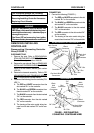
7. Align the mounting hole in the NEW brake re-
lease lever with the mounting hole in the motor
brake assembly.
8. Secure the NEW brake release lever to the mo-
tor/brake assembly using the NEW mounting
screw and self-locking nut. Securely tighten.
9. Align the two (2) mounting holes in the EXIST-
ING brake cover with the two (2) mounting holes
in the motor/brake assembly.
10. Secure the EXISTING brake cover to the motor/
brake assembly using the two (2) EXISTING mount-
ing screws and spring washers. Securely tighten.
11. Reinstall the rear shroud. Refer to
REMOVING/IN-
STALLING THE REAR SHROUD in PROCEDURE
9 of the Owner’s Manual, part number 1090132.
12. Reinstall the seat. Refer to
REMOVING/IN-
STALLING THE SEAT in PROCEDURE 5 of the
Owner’s Manual, part number 1090132.
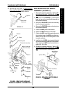
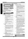
Panther MX - 4
1. Remove the seat. Refer to REMOVING/IN-
STALLING THE SEAT in PROCEDURE 5 of the
Owner’s Manual, part number 1090132.
2. Remove the rear shroud. Refer to
REMOVING/IN-
STALLING THE REAR SHROUD in PROCEDURE
9 of the Owner’s Manual, part number 1090132.
3. Remove the socket screw and the bolt socket
securing the brake release lever to motor/brake
assembly.
4. Remove the brake release lever.
5. Align the mounting holes in the NEW brake re-
lease lever with the mounting holes in motor/brake
assembly.
6. Secure the NEW brake release lever to the mo-
tor/brake assembly using the NEW socket screw
and bolt socket. Securely tighten.
7. Reinstall the rear shroud. Refer to
REMOVING/
INSTALLING THE REAR SHROUD in PROCE-
DURE 9 of the Owner’s Manual, part number
1090132.
8. Reinstall the seat. Refer to
REMOVING/IN-
STALLING THE SEAT in PROCEDURE 5 of the
Owner’s Manual, part number 1090132.
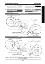
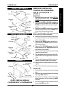
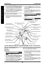
FIGURE 4 - REPLACING BRAKE RELEASE
LEVER ASSEMBLY
PANTHER MX - 4
Mounting Screws
Spring Washers
Brake
Cover
Motor/Brake
Assembly
Mounting
Screw
Self-locking
nut
Brake
Release
Lever
Socket
Screw
Bolt
Socket
Brake Release Lever
Motor/Brake
Assembly
Mounting Holes
ALL MODELS EXCEPT PANTHER MX - 4