


5656
O
P
T
I
O
N
S
PROCEDURE 12 OPTIONS
This Procedure Includes the Following:
Preparing the Scooter for Left Hand
Operation
WARNING
After ANY adjustments, repair or service and
BEFORE use, make sure that all attaching hard-
ware is tightened securely - otherwise injury or
damage may occur.
Turn Power OFF and remove key from igni-
tion. Disconnect battery harness from the
motor lead.
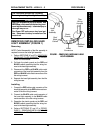
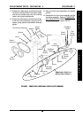
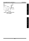
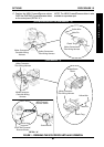
PREPARING THE SCOOTER FOR
LEFT HAND OPERATION
(FIGURE 1)
1. Remove the seat. Refer to REMOVING/IN-
STALLING THE SEAT in PROCEDURE 5 of the
Owner’s Manual, part number 1090132.
2. Remove the rear shroud. Refer to
REMOVING/IN-
STALLING THE REAR SHROUD in PROCEDURE
9 of the Owner’s Manual, part number 1090132.
3. Remove the batteries. Refer to
REMOVING IN-
STALLING BATTERIES WITH CABLES in PRO-
CEDURE 4 of the Owner’s Manual, part number
1090132.
4. Peform one (1) of the following:
ALL models EXCEPT the PANTHER MX - 4 -
A. Disconnect the YELLOW connector of the
tiller wiring harness from the YELLOW con-
nector of the controller wiring harness.
PANTHER MX - 4 -
A. Disconnect the WHITE connector of the tiller
wiring harness from the WHITE connector
of the controller wiring harness.
B. Gently pull open the hinged strain relief on
the rear of the WHITE connector of the tiller
wiring harness.
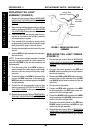
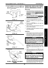
5. Locate the YELLOW wire coming out of the rear
of the YELLOW or WHITE connector (depend-
ing on scooter model) of the tiller wiring harness.
6. Insert a small, pointed tool into the FRONT of the
YELLOW or WHITE connector (depending on
scooter model) of the tiller wiring harness, directly
under the MALE pin of the YELLOW wire.
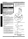
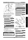
7. Push up on and hold the plastic tang under the
male pin of the YELLOW wire.
8. While perfoming STEP 7, pull the YELLOW wire
out from the back of the YELLOW or WHITE
connector (depending on scooter model) of the
tiller wiring harness.
9. Repeat STEPS 5-8 for the ORANGE wire com-
ing out of the rear of the YELLOW or WHITE
connector (depending on scooter model) of the
tiller wiring harness.
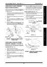
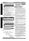
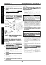
10. Align the MALE pin of the YELLOW wire with the
slot formerly occupied by the MALE pin of the
ORANGE wire in the REAR of the YELLOW or
WHITE connector (depending on scooter model)
of the tiller wiring harness.
11. Push the MALE pin of the YELLOW wire for-
ward through the slot until it “clicks” into place.
12. Repeat STEPS 10-11 to position the MALE pin
of the ORANGE wire into the slot fromerly occu-
pied by the MALE pin of YELLOW wire.
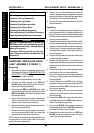
NOTE: WHEN the YELLOW or WHITE connector
(depending on scooter model) of the tiller wiring har-
ness and the YELLOW or WHITE connector (de-
pending on scooter model) of the controller wiring
harness are reconnected, the mating of the wires
coming out of the rear of the connectors should be
YELLOW to ORANGE.
13. Perform one (1) of the following:
ALL models EXCEPT the PANTHER MX - 4 -
A. Reconnect the YELLOW connector of the
tiller wiring harness to the YELLOW connec-
tor of the controller wiring harness.
PANTHER MX - 4 -
A. Gently close the hinged strain relief on the
rear of the WHITE connector of the tiller wir-
ing harness.
B. Reconnect the WHITE connector of the tiller
wiring harness to the WHITE connector of
the controller wiring harness.
14. Reinstall the batteries. Refer to
REMOVING IN-
STALLING BATTERIES WITH CABLES in PRO-
CEDURE 4 of the Owner’s Manual, part number
1090132.
15. Reinstall the rear shroud. Refer to
REMOVING/
INSTALLING THE REAR SHROUD in PROCE-
DURE 9 of the Owner’s Manual, part number
1090132.
16. Reinstall the seat. Refer to
REMOVING/IN-
STALLING THE SEAT in PROCEDURE 5 of the
Owner’s Manual, part number 1090132.