1818
T
I
L
L
E
R
PROCEDURE 4 TILLER
Section F - Removing/Installing Tiller
From/To Front Frame Assembly
(FIGURE 8)
REMOVING.
1. Slowly pull the tiller wiring harness through the
hole in the shroud assembly, until the tiller as-
sembly is free from the front frame assembly
(DETAIL “A”).
2. Pull the base handle bar joint from the front frame
assembly (DETAIL “B”).
3. Remove the boot. Refer to
REMOVING/INSTALL-
ING BOOT in this procedure of this manual.
4. Refer to the chart on page 11 of this manual to
determine which section(s) need to be performed
next to successfully complete the removal/instal-
lation of the tiller assembly.
INSTALLING.
1. Reinstall the boot. Refer to
REMOVING/INSTALL-
ING BOOT in this procedure of this manual.
2. Position the base handle bar joint in the front frame
assembly, making sure the mounting holes in the
base handle bar joint line up with the mounting
holes in the front frame assembly (DETAIL “A”).
3. Slowly thread the tiller wiring harness through the
hole in the shroud, until most of the tiller wiring har-
ness is on the underside of the front frame assembly.
4. Refer to the chart on page 11 of this manual to
determine which section(s) need to be performed
next to successfully complete the removal/instal-
lation of the tiller assembly.
Section E - Disconnecting/Connecting
Base Handle Bar Joint From/To Front
Frame Assembly (FIGURE 7)
DISCONNECTING.
1. Remove the two (2) bolts and self-locking nuts
securing the base handle bar joint (and for the
LYNX LX - 3 ONLY, the head light assembly) to
the front frame assembly.
2. Refer to the chart on page 11 of this manual to
determine which section(s) need to be performed
next to successfully complete the removal/instal-
lation of the tiller assembly.
CONNECTING.
1. Align the two (2) mounting holes in the base
handle bar joint with the two (2) mounting holes
in the front frame assembly.
2. For the LYNX LX - 3, align the two (2) mounting
holes in the head light assembly with the two (2)
mounting holes in the front frame assembly and the
two (2) mounting holes in the base handle bar joint.
3. Secure the base handle bar joint (and for the
LYNX LX - 3, the head light assembly) to the
front frame assembly using the two (2) bolts and
self-locking nuts. Securely tighten.
4. Refer to the chart on page 11 of this manual to
determine which section(s) need to be performed
next to successfully complete the removal/instal-
lation of the tiller assembly.
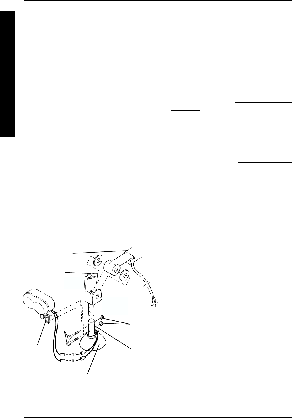
FIGURE 7 - DISCONNECTING/
CONNECTING BASE HANDLE BAR JOINT
FROM/TO FRONT FRAME ASSEMBLY
Base Handle
Bar Joint
Bolts
Self-
locking
nuts
Front
Frame
Assembly
Boot
Head
Light
Assembly
(LYNX
LX - 3
ONLY)
Tiller Assembly


