


5151
R
E
P
L
A
C
E
M
E
N
T
P
A
R
T
S
PROCEDURE 11REPLACEMENT PARTS - PANTHER MX - 4
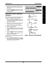
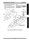
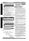
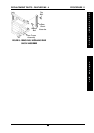
FIGURE 3 - REPLACING TAIL LIGHT CABLES
Plastic
Guards
Red And Black
Cables
Tail Light
Cable
Tail Light
Assembly
Metal
Connectors
REPLACING DISC BRAKE
ASSEMBLY (FIGURE 4)
Removing The Disc Brake Assembly
1. Remove the seat. Refer to REMOVING/IN-
STALLING THE SEAT in PROCEDURE 5 of the
Owner’s Manual, part number 1090132.
2. Remove the rear shroud. Refer to
REMOVING/IN-
STALLING THE REAR SHROUD in PROCEDURE
9 of the Owner’s Manual, part number 1090132.
3. Remove the rear wheels. Refer to
REMOVING/IN-
STALLING THE REAR WHEELS in PROCEDURE
9 of the Owner’s Manual, part number 1090132.
4. Disconnect the hand brake cable assembly.
Refer to
REMOVING/INSTALLING TILLER AS-
SEMBLY, SECTION “B” - DISCONNECTING/
CONNECTING HAND BRAKE CABLE ASSEM-
BLY in PROCEDURE 4 of this manual.
5. Remove the four (4) hex - cap screws and spring
washers securing the disc brake assembly to the
transaxle assembly.
6. Remove the disc brake assembly.
7. Align the NEW disc brake assembly with the
mounting holes in the transaxle assembly.
CAUTION
DO NOT overtighten the four (4) hex cap
screws securing the disc brake assembly to
the transaxle assembly. Otherwise, damage
to the disc brake assembly may occur.
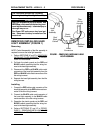
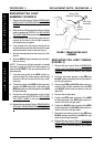
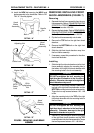
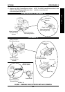
FIGURE 4 - REPLACING DISC BRAKE
ASSEMBLY
Hex
Cap
Screws
Spring
Washers
Disc Brake
Assembly
Transaxle
Assembly
Spring
Washers
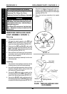
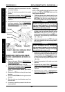
REPLACING DISC BRAKE SHOES
(FIGURE 5)
1. Remove the seat. Refer to REMOVING/IN-
STALLING THE SEAT in PROCEDURE 5 of the
Owner’s Manual, part number 1090132.
2. Remove the rear shroud. Refer to
REMOVING/
INSTALLING THE REAR SHROUD in PROCE-
DURE 9 of the Owner’s Manual, part number
1090132.
3. Remove the rear wheels. Refer to
REMOVING/
INSTALLING THE REAR WHEELS in PROCE-
DURE 9 of the Owner’s Manual, part number
1090132.
Rear Shroud
8. Secure the NEW disc brake assembly to the
transaxle assembly using the four (4) NEW hex -
cap screws and spring washers. Torque the hex
cap screws between 43 - 61 in./lbs.
9. Reconnect the hand brake cable assembly. Re-
fer to
REMOVING/INSTALLING TILLER AS-
SEMBLY, SECTION “B” - DISCONNECTING/
CONNECTING HAND BRAKE CABLE ASSEM-
BLY in PROCEDURE 4 of this manual.
10. Reinstall the rear wheels. Refer to
REMOVING/IN-
STALLING THE REAR WHEELS in PROCEDURE
9 of the Owner’s Manual, part number 1090132.
11. Reinstall the rear shroud. Refer to
REMOVING/IN-
STALLING THE REAR SHROUD in PROCEDURE
9 of the Owner’s Manual, part number 1090132.
12. Reinstall the seat. Refer to
REMOVING/IN-
STALLING THE SEAT in PROCEDURE 5 of the
Owner’s Manual, part number 1090132.
P
A
N
T
H
E
R
M
X
4