


BENDIX/KING KLN 90B
Rev 5, April/2003 10521I05.TDC Page 2-67
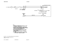
1. The 12th and 13th harmonics of the above mentioned frequencies can be radiated from the
VHF COMM at a level strong enough to be a problem to the GPS but still be well low enough
to meet TSO requirements for the VHF COMM. If the interference is from the radiating VHF
COMM, an optional notch filter (i.e. the KA 198 P/N 071-01565-0000 or TED Mfg 4-70-54)
will need to be installed. The recommended location for the inline filter should be as close
to the VHF RT as practical.
NOTE
The conditions and tests performed on this article
are minimum performance standards. It is the re-
sponsibility of those desiring to install this article ei-
ther on or within a specific type or class of aircraft to
determine that the aircraft installation conditions are
within these performance standards. The article may
be installed only if further evaluation by the applicant
documents an acceptable installation and is ap-
proved by the Administrator
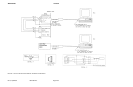
2. The other possibility is re-radiation from an ELT. The radiated RF from the VHF COMM can
excite the output tank circuit of the ELT and cause it to oscillate and radiate RF strong
enough to interfere with the GPS. If disconnecting the ELT antenna eliminates the GPS in-
terference, the manufacturer of the ELT should be contacted for a recommended solution.
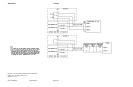
2.4.4 INTEGRATED INSTALLATION CHECK OUT
The following paragraphs define checkout procedures for all possible Input/Output signals that
can be connected to the KLN 90B. It should be clearly determined which of the signals are in-
tended to be used in any given installation and then only the paragraphs pertaining to those
signals should be performed.
2.4.4.1 All Installations
Perform all steps defined in Paragraph 2.4.3 and leave the system energized with a valid GPS
signal being received.
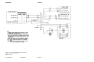
2.4.4.2 EFIS or CDI/HSI Interface
Cycle the power on the KLN 90B which will cause the self test page to be displayed. Verify that
the CDI needle, after it has settled, is indicating half scale right deflection. Verify that the TO/
FROM flag is indicating FROM. Verify that the nav flag is pulled from view.
Verify the selected course from the EFIS or CDI/HSI is interfaced properly to the KLN 90B in
the OBS Mode. The OBS Mode can be selected by two methods:
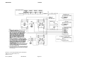
1. In IFR Non-Precision Approach configurations, the OBS/LEG selection will usually be con-
trolled by means of a GPS CRS external switch/annunciator. Each press of the switch/ an-
nunciator will cause the mode to change between OBS and LEG.
2. In VFR or IFR Enroute/Terminal configurations, the OBS/LEG selection will usually be con-
trolled through the front panel controls of the KLN 90B. Select the Mode Page 2 on the left.
If the OBS mode is not active, press the enter button.
Verify that the selected course value on the Mode Page 2 agrees with the value displayed
on the EFIS Course Pointer or the HSI Course Pointer, if it is a remotely driven type. Press
the left cursor button and modify the selected course value. Again, verify the course pointer
tracks the new value. Change the selected course value on the EFIS, HSI or CDI using the