


BENDIX/KING KLN 90B
Page 1-6 10521I05.TDC Rev 5, April/2003
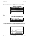
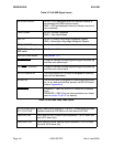
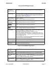
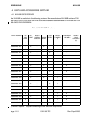
Table 3-7 KLN 90B Signal Inputs
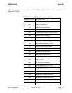
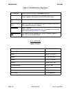
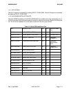
Table 3-8 KLN 90B Gray Code Inputs
GPS DISPLAYED: OPEN = GPS displayed (when an indicator resolver is
connected to the OBS resolver inputs)
GND = GPS not displayed (when an indicator resolver is
not connected)
TAKE HOME: OPEN = Normal Operation
GND = Take Home Mode
SDI 1/2: OPEN = Primary Long-range Navigation System
GND = Secondary Long-range Navigation System
EFIS 429 RCVR inputs: See Section 1.3.1
RDRG (Radar Graphics)
429 inputs:
See Section 1.3.1
AIR DATA 429 Inputs: See Section 1.3.1
ARM SELECT: This pin is used as a mode programming pin on power-up
and later as a select input.
LEG/OBS CONTROL: This pin is used as a mode programming pin on power-up
and later as a control input.
DATA LOADER IN: The Data Loader RS 232 input is designed to communi-
cate with the dataloader
RS 232 IN: The RS 232 input is designed to communicate with devic-
es, i.e. air data and fuel flow sensors via RS 232 format
(refer to Appendix A)
ALT ALERT: ENABLED = Open (or tied to A/C Power thru a passive
load)
DISABLED = GND (This pin also functions as an output,
refer to section 2.3.6.2.X. for details)
(A1,A2,A4,B1,B2,B
4,C1,C2,C4,D4)
Gray Code Altitude Signals (0 V. to 28 V.) These inputs are diode
isolated inside the KLN 90B on all units above S/N 1542
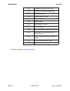
OBS RES SIN: OBS resolver sine, nominal input impedance = 36.5 K ohms (ac)
and 100 K ohms (dc)
OBS RES COS: OBS resolver cosine, nominal input impedance = 36.5 K ohms
(ac) and 100 K ohms (dc)