BENDIX/KING KLN 90B
Page 2-6 10521I05.TDC Rev 5, April/2003
O. Pins 23 and 24; GPS 429 Transmitter outputs
Pins 23 and 24 are the GPS ARINC 429 transmitter output port of the KLN 90B.
For specific label information transmitted on this bus refer to Paragraph 1.3.1 in
Section 1 of this manual.
P. OBS Resolver Interface
Pin 26; OBS Resolver Sine
Pin 31; OBS Resolver Out
Pin 37; OBS Resolver Cosine
This interface is compatible with indicators that are electrically zeroed (EZ) at
300 degrees and indicators that are omni-ranged zero at 300 degrees. This in-
terface will operate properly with either "0.85 gain" resolvers or "0.41 gain" re-
solvers with no special programming requirements.
OBS Resolver Out is a 450 Hz output used to excite the resolver. The resolver
output voltage is then received by the OBS Resolver sine and cosine inputs.
Refer to section 2.4.1, KLN 90B OBS Resolver Calibration Procedure for 30 Hz
indicator calibration.
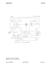
Q. Pin 27; A/C GROUND
Pin 27 is tied to aircraft ground. Wiring harness shields are not to be terminated
on this pin. Refer to figure 2-17.
R. Pins 28, 29, and 32; 28 V Light/Light Lo, 14 V/5 V Light, and Light Lo
Pins 28, 29, and 32 are the pins used for the panel lighting. Refer to the inter-
connect drawing for the correct method of connecting these pins and connecting
to the aircraft dimmer bus.
S. Pin 30; Approach Arm Select
Pin 30 is used as a mode programming pin on power-up and later as a select
input. If the installation is not certified for approach, the external switch/annun-
ciator is not required. This function can be eliminated by connecting the AP-
PROACH ARM SELECT, pin 30, to the APPROACH ARM ANNUNCIATOR, pin
17. On power- up, it will be monitored to determine whether external switches
are installed. If the installation is approved for approach and the external switch/
annunciator is installed, then a momentary ground on pin 30 will alternately arm
or disarm the approach mode.
T. Pin 33;LEG/OBS
CONTROL
Pin 33 is used as a mode programming pin on power-up and later as a select
input. If the installation does not require an external switch/annunciator to select
the OBS mode, then connect the LEG/OBS CONTROL, pin 33, to the + TO, pin
21. On power-up, it will be monitored to determine whether external switches are
installed. If the external switch/annunciator is not installed, the selection of OBS
and LEG will be performed by means of the left inner and outer knobs on the
MODE page. If the installation is approved for approach and the external switch/
annunciator is installed, then a ground on pin 33 will switch the unit between
LEG and OBS modes. The MODE page on the left inner and outer knob will be
disabled.


