


9308–287
Service
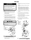
WARNING
Installing and servicing this equipment requires
access to parts that may cause electric shock or
other serious injury if the work is not performed
properly
. Do not install or service this equipment
unless you are trained and qualified.
T
o reduce the risk of serious injury whenever you
are instructed to relieve pressure, always follow the
Pressure Relief Procedure
on page 6.
NOTE:
Check all possible remedies in the
Trouble-
shooting
section before disassembling the meter
.
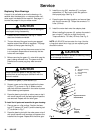
1.
Relieve the pressure
and flush the meter as
described on page 7.
2.
Disconnect the fiber optic cable(s) (G) from the
electronic module (B). See Fig. 3.
3.
Disconnect the air hose fitting and remove the air
hose from the motor
. Disconnect both fluid hose
fittings and remove the fluid hose from the meter
.
4.
Remove the four screws (A) to separate the gear
housing (F) from the manifold.
CAUTION
Never remove the electronic module (B) from the top
gear housing (E). The electronic module is calibrated
to the gear housing assembly and will not function
properly if removed.
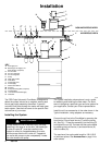
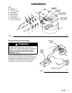
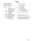
Fig. 3
G
B
E
F
A
C*
Torque
to 7.5
ft-lb (10 N
Sm)
D
01851
KEY
A Screw
B
Electronic Module
C O-Ring
D Manifold
ET
op Gear Housing
F
Gear Housing Assy
.
G
Fiber Optic Cable
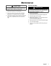
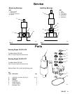
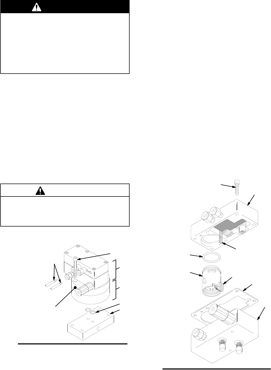
Replacing the Turbine Alternator
1. Remove
the top chassis (3) from the bottom
chassis (2). See Fig. 4.
2.
Disconnect the 3-pin connector (J) from the square
pins (H).
3.
Carefully pull the alternator (4) away from the top
housing.
4.
Using an ohmmeter
, test the coil in the turbine
alternator
. Measure the resistance between the
two outer terminals of the 3-pin connector (J). The
resistance should be 3–5 ohms. If the reading
varies from this value, replace the alternator (4).
5.
Lubricate the alternator o-ring (4a) seal with petro
-
leum jelly
.
6.
Insert the alternator (4) into the top chassis (3).
7.
Connect the 3-pin connector (J) to the 3 square
pins (H) in the top chassis (3).
8.
Check to see that the gasket (5) is not damaged. If
damaged, replace the gasket.
9.
Snap the top and bottom chassis together
.
10.
Install and tighten the chassis screws (9) to 40
in-lbs (4.52 N
Sm).
Fig. 4
3
2
J
H
4
4a
5
9
0180A
KEY
H Pins
J 3-pin
Connector
2
Bottom Chassis
3T
op Chassis
4 Alternator
4a
Alternator O-Ring
5 Gasket
9 Chassis Screws
T
orque to
40 in-lb
(4.52 N
Sm)