


5308–287
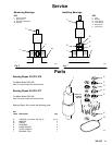
Installation
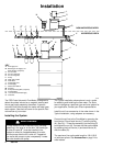
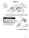
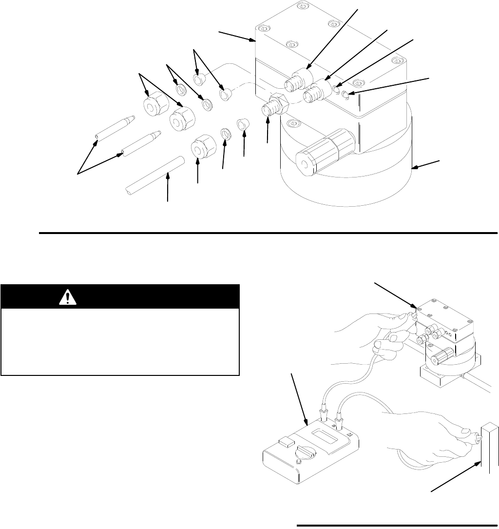
Fig. 1
KEY
A Tubing,
1/4” OD
B
Nut (nylon)
C
Ferrule, back (nylon)
D
Ferrule, front (nylon)
E
Air Inlet Fitting
F
Electrical Chassis
G
Fiber Optic Cables
H
Gear Housing Assy
.
J
Nut (aluminum)
K
Ferrule, back (aluminum)
L
Ferrule, front (aluminum)
J
A
C
D
E
F
H
G
Flow
Indicator
Light
(Green)
Power Indicator
Light
(Yellow)
Fiber
Optic
Sender
1
Fiber
Optic
Sender
2
K
L
B
01849
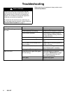
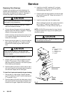
Check the Electrical Grounding
WARNING
Proper
electrical grounding of your system is
essential when used with flammable or combustible
liquids. For you safety
, read the warning section
FIRE, EXPLOSION, AND ELECTRIC SHOCK
HAZARD
on page 2.
Have a qualified electrician check the electrical
grounding continuity between the flow meter electrical
chassis and a true earth ground as shown in Fig. 2. If
the resistance is greater than 25 ohms, check the
mounting or add a ground strap to the chassis.
Fig. 2
True Earth Ground
Digital
Voltage
Meter
Electrical
Chassis
01850