


10 308–287
Service
Replacing Worn Bearings
A
repair kit is available to service the bearings. An
asterisk after the description or reference letter indi
-
cates a part included with the repair kit. See page 1
1
to order the proper kit for your meter model.
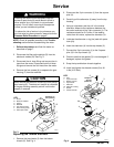
CAUTION
This is a close-tolerance device. It will be damaged if
forced apart during disassembly
.
1.
Loosen the four screws (N). See Fig. 5. Leave
about two threads connected.
2.
The two halves of the gear housing are pegged
together and will be dif
ficult to separate. The pegs
are part of the top gear housing (E).
Hold the housing and tap the screws one at a time
in a consistent sequence and eventually the two
halves will come apart.
3.
Before removing the gears (L), note which peg the
gear is being removed from. The gears must be
installed on the same peg they were removed
from.
CAUTION
Always reinstall the gears on the peg they were
removed from to ensure proper calibration with the
electronic module.
4.
Remove the gears (L) and washers (K).
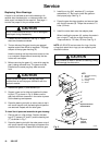
5.
Support a gear on its sides and position the bear
-
ing tool (T*) as shown in Fig. 6. Make sure the
gear has suf
ficient clearance in the center to press
out the bearings and spacers.
6.
Press the bearing tool with an arbor press or tap it
with a soft hammer until the bearings and spacers
are removed. Repeat with the other gear
.
To install th
e k
it part
s a
nd assemble the gea
r h
ousing:
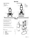
1.
Place a gear on a flat surface. Position the bear
-
ings (P*), spacers (R* and S*) and the bearing tool
(T*) as shown in Fig. 7.
2.
Press the bearing tool with the arbor press or tap it
with a soft hammer until bearings and spacers are
installed into the gear
. Repeat with the other gear
.
3.
Install the o-ring (M*), washers (K*), and gear
assemblies (L*). Be sure to install the gears on
their proper pegs. See Fig. 5.
4.
Press the gear housings together and secure them
with the four screws (N). T
orque the screws to 7.5
ft-lbs (10 N
Sm).
5.
Install the meter back onto the adapter plate.
When installing the screws (A), replace the meter
’s
two o-rings (C*) with the o-rings from the kit.
T
orque screws to 7.5 ft-lbs (10 N
S
m). See Fig. 3.
NOTE:
Kit 223–276 has two sets of o-rings. Use the
o-rings that match the o-rings you are replacing and
discard the others.
CAUTION
Never immerse a meter in solvent for cleaning. Doing
so will damage the electronics.
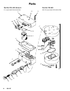
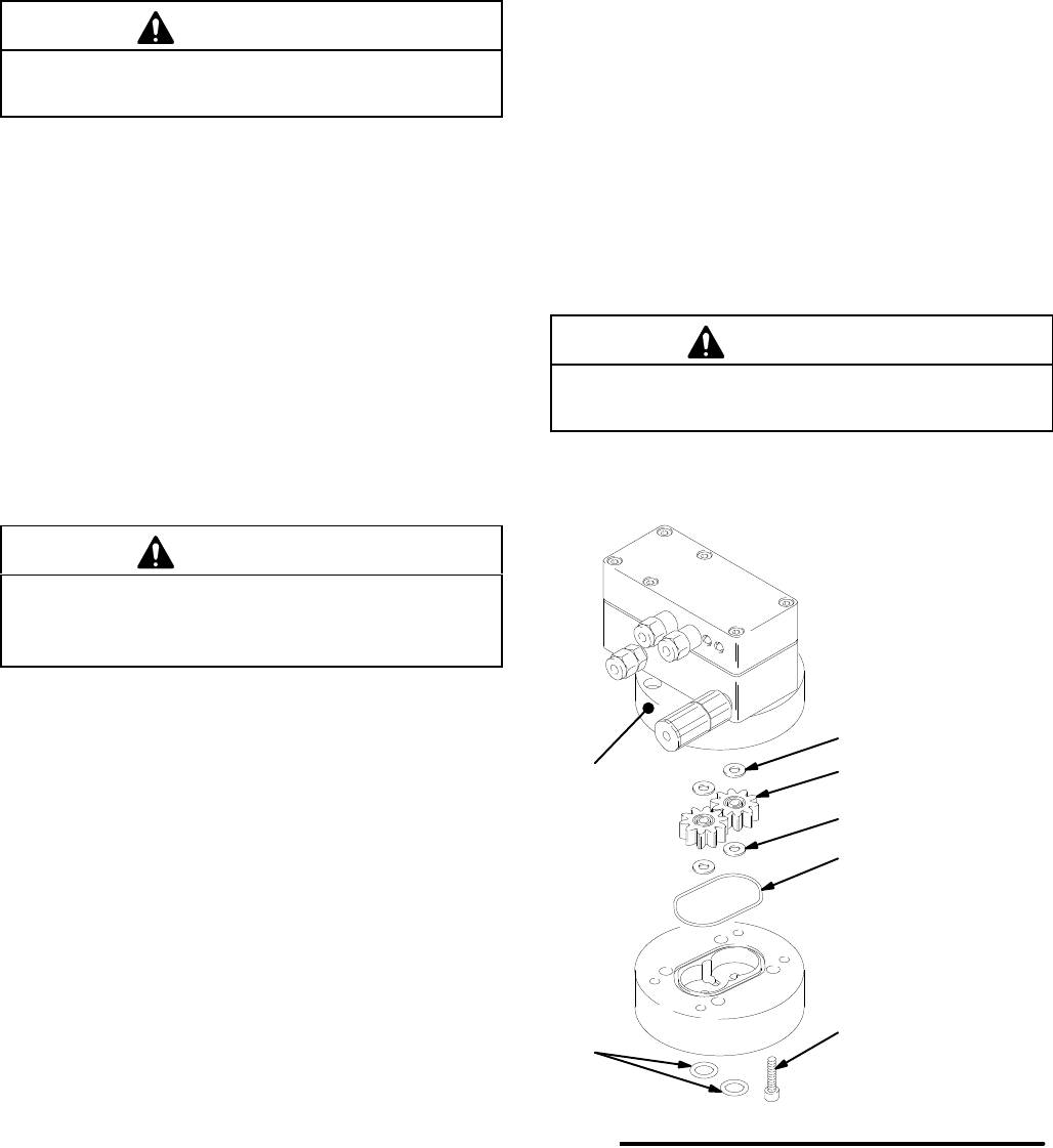
Fig. 5
K*
LE
N
Torque
to
7.5 ft-lb
(10 N
Sm)
M*
K*
01852A
KEY
ET
op Gear Housing
K Washer
L
Gear Assembly
M O-Ring
N Screw
1b
Replace
whenever
disassembled