


4 308–287
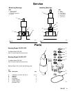
Installation
AB
2
CD E
G
H
B
1
CDE
F
J
K
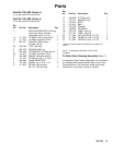
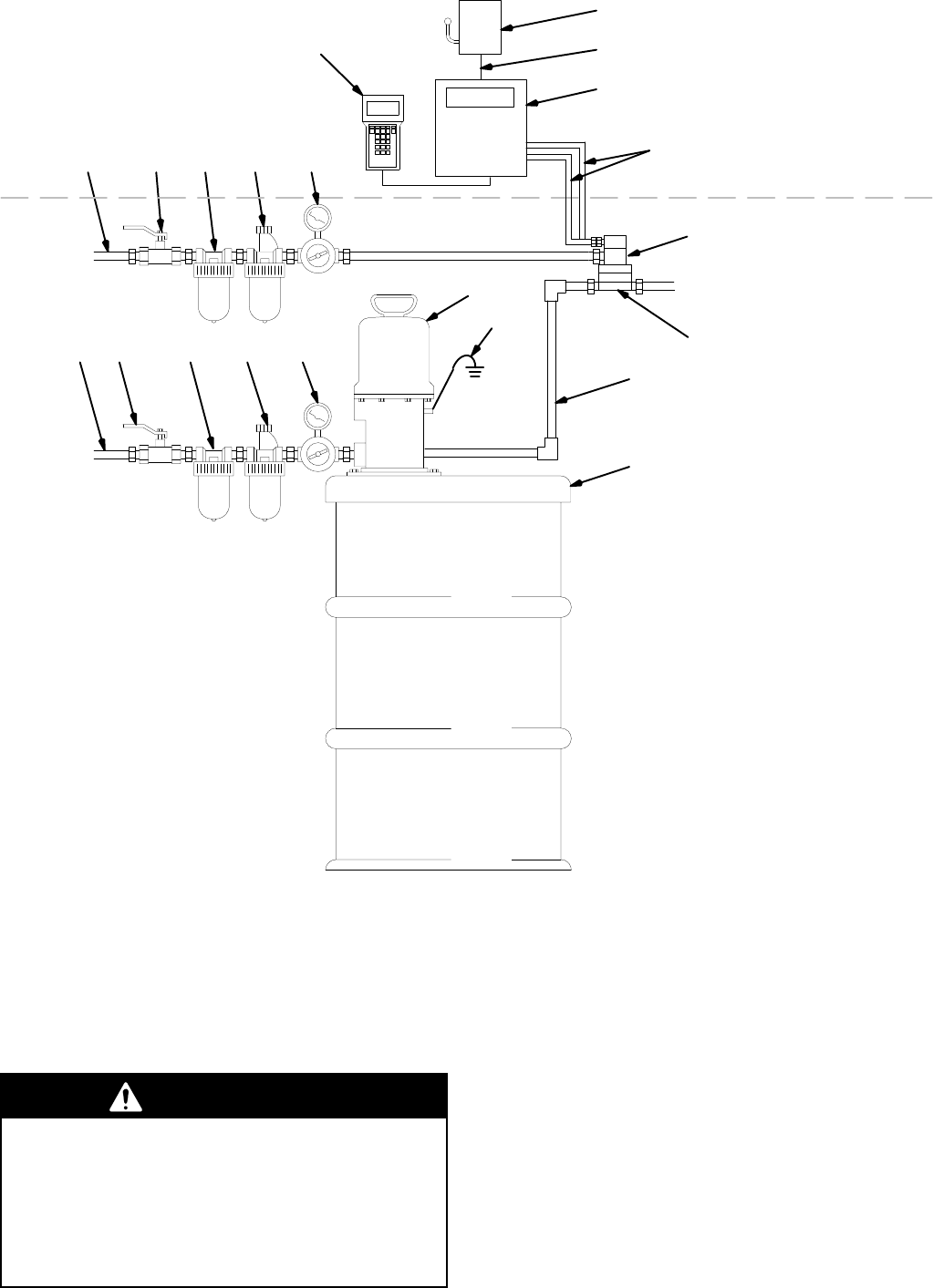
KEY
A Air
Supply Line
B Bleed-T
ype Air Supply Line
Shut-of
f V
alve
(required)
C
Air Line Filter
D
Air Line Lubricator
E
Air Line Regulator
F Pump
G
Fiber Optic Cable
H
Flow Meter
J
Fluid Supply Line
K
Fluid Supply
L
Main Power Switch
M Pendant
N
Pump Grounding Wire
(required)
P
Fluid Manifold
R 1
15V 60 Hz Electrical Supply
S Controller
L
M
N
NON-HAZARDOUS
AREA
HAZARDOUS AREA
A
P
01848
R
S
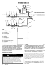
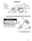
The PRO Pulse V
olumetric Flow Meter is designed to
detect the pulses induced on a magnetic sensor each
time a gear tooth passes by the sensor
. A specific
volume of fluid flows through the meter with each gear
tooth rotation. See the front cover for the specific fluid
volume flow of your meter
.
Installing the System
WARNING
To
help reduce the risk of serious injury
, including
splashing in the eyes or on the skin, the bleed-type
air shut-of
f valve (B
1
) must be installed in the
system to relieve air trapped between this valve
and the pump after the air is shut of
f. T
rapped air
can cause the pump to cycle unexpectedly
. Locate
the valve close to the pump.
The T
ypical Installation shown above is only a guide
for selecting and installing the flow meter
. For assis
-
tance in designing a particular type and size system for
your application, contact your Graco representative.
Install the air line accessories in the order shown in the
T
ypical Installation, using adapters as necessary
.
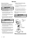
Connect the air line to the Flow Meter by pressing the
front ferrule (D) and back ferrule (C) onto the tubing
(A). See Fig. 1. Press the assembly into the fitting (E)
and tighten the nut (A). Connect the fiber optic cables
by pressing the front ferrule (L) and back ferrule (K)
onto the cable (G).
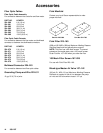
The maximum fiver optic cable length is 100 ft (30.5
m) with two splices. See
Accessories
on page 14 to
order cables.