


308351 9
Installation (Air–Powered Pumps)
WARNING
A main air bleed valve (C), pump air bleed valve
(E), and fluid drain valve (M) are required. These
accessories help reduce the risk of serious injury,
including fluid injection and splashing of fluid in the
eyes or on the skin, and injury from moving parts if
you are adjusting or repairing the pump.
The main air bleed valve (C) shuts off the air to the
pump and ram. The pump air bleed valve (E)
relieves air trapped between this valve and the
pump after the air is shut off. Trapped air can
cause the pump to cycle unexpectedly. Locate the
valve close to the pump. Order Part No. 107141.
The fluid drain valve assists in relieving fluid pres-
sure in the displacement pump, hose, and gun.
Triggering the gun to relieve pressure may not be
sufficient. Order Part No. 210658.
Air Line Accessories
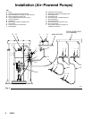
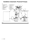
Install the following accessories in the order shown in
Fig. 3, using adapters as necessary:
D An air line lubricator (D) provides automatic air
motor lubrication. Locate in the position shown.
D A main air bleed valve (C) is required in your
system to shut off the air supply to the pump and
ram (see the WARNING above). When closed, the
valve will bleed off all air in the ram and pump, and
the ram will slowly lower. Be sure the valve is easily
accessible from the pump, and is located upstream
from the air manifold (G).
D A pump air bleed valve (E) is required in your
system to relieve air trapped between it and the air
motor when the valve is closed (see the WARNING
at left). Be sure the bleed valve is easily accessible
from the pump, and is located downstream from
the air regulator.
D An air regulator (F) controls pump speed and
outlet pressure by adjusting the air pressure to the
pump. Locate the regulator close to the pump, but
upstream from the pump air bleed valve.
D A pump runaway valve (V) senses when the
pump is running too fast and automatically shuts off
the air to the motor. A pump which runs too fast can
be seriously damaged. Locate in the position
shown.
D An air manifold (G) has a swivel air inlet. It
mounts to a ram, and has ports for connecting lines
to air accessories, such as the ram air regulator
(T) and ram director valve (U).
D An air line filter (J) removes harmful dirt and
moisture from the compressed air supply. Also,
install a drain valve (W) at the bottom of each air
line drop, to drain off moisture.
D An air shutoff valve (K) isolates the air line acces-
sories for servicing. Locate upstream from all other
air line accessories.
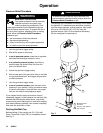
Fluid Line Accessories
Install the following accessories in the positions shown
in Figs. 3 and 4, using adapters as necessary:
D Install a fluid shutoff valve (P) at each gun/valve
drop, to isolate the gun/valve and fluid accessories
for servicing.
D Install a fluid drain valve (M) near the pump fluid
outlet, and at each gun/valve station. The drain
valves are required in your system to relieve fluid
pressure in the displacement pump, hose and
gun/valve (see the WARNING at left). Drain valves
at the gun/valve stations may be mounted in the
base of a fluid regulator (L), using an adapter.
D A fluid regulator (L) controls fluid pressure to the
gun/valve, and dampens pressure surges.
D A gun or dispense valve (S) dispenses the fluid.
The gun shown in Fig. 3 is a high pressure dispens-
ing gun for highly viscous fluids.
D A gun/valve swivel (R) allows freer gun/valve
movement.