


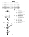
308351 23
Displacement Pump Service
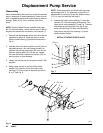
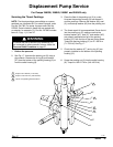
Reassembly
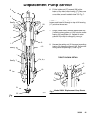
Fig. 16 shows a cutaway of the entire pump.
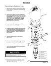
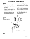
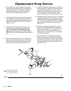
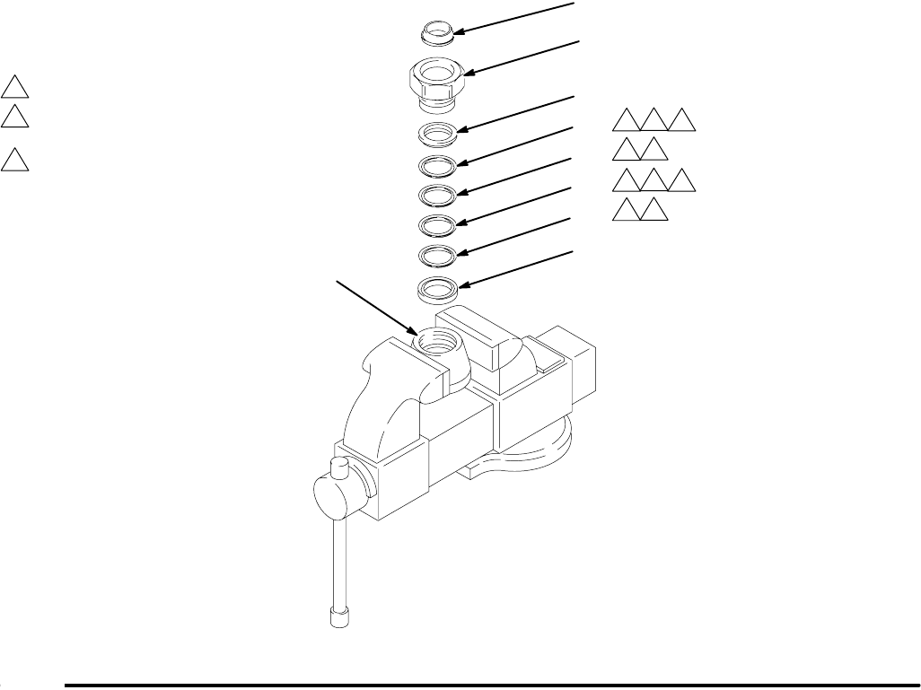
1. Lubricate the intake packings and install them in
the valve body (16), with the lips of the v-pack-
ings facing up. Install the v-packings in the order
shown in Fig. 13.
2. With the beveled side facing up, press the intake
valve seal (39*) into the recess of the intake valve
packing nut (15) until it snaps into place. The nose
of the seal should be flush with or slightly recessed
into the face of the packing nut.
3. Place the flats of the valve body (16) in a vise.
Screw the packing nut into the valve body hand-
tight. Set the intake housing assembly aside.
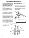
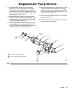
4. Lubricate the piston seal (13*) and install it on the
piston seat (14). Apply thread sealant to the
threads of the seat and the piston guide (11).
Screw the guide onto the seat (14). Place the
guide in a vise as shown in Fig. 11 and torque the
seat to 77–85 N.m (57–63 ft-lb).
5. If it was necessary to remove the priming piston
rod (18) from the piston (12), place the flats of the
piston in a vise. Using an adjustable wrench on the
flats of the rod, screw the rod into the piston.
Torque to 125–139 N.m (92–102 ft-lb). Be careful
not to create burrs on the flats of the rod.
6. Place the piston seat/guide assembly onto the
piston (12) so the 45_ beveled seating surfaces
match. Screw the displacement rod (1) into the
piston (12) hand tight, then torque the rod to
324–368 N.m (239–271 ft-lb).
04225
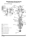
Fig. 13
1
2
39*
15
Lubricate.
Lips of v-packings must face up.
1
2
1
2
1
2
1
2
23*
26*
24*
24*
25*
16
Model 236611 Displacement Pump Shown
3
Optional Displacement Pump 237945
uses all PTFE v-packings (item 24).
3
3
26*