


24 308351
Displacement Pump Service
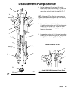
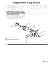
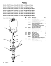
7. If the cylinder (10) was removed from the outlet
housing (9), lubricate the seal (8*) and place it on
the top of the cylinder. (The cylinder is symmetri-
cal, so either end can be the top.) Screw the
cylinder into the outlet housing. See Fig. 16.
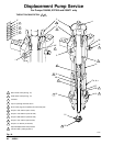
8. Lubricate the seal (42*) and install it in the groove
on the bottom of the packing housing (3). Screw
the packing housing into the outlet housing (9) and
torque to 176–258 N.m (130–190 ft-lb). See the
Detail in Fig. 16.
9. Lubricate the throat packings and glands, and
install them in the packing housing (3) one at a
time, with the lips of the v-packings facing
down. Install the v-packings in the order shown in
the Detail in Fig. 16. Loosely install the packing nut
(2).
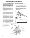
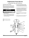
10. Lubricate the displacement rod (1). Slide the rod,
piston assembly, and priming piston rod (18) into
the cylinder (10) from the bottom, until the top of
the rod (1) protrudes from the packing nut (2).
11. Lubricate the seal (8*) and install it on the bottom
of the cylinder (10). Slide the intake valve housing
(17) onto the priming piston rod (18), making
certain that the smooth surface of the valve stop
(VS) is facing down toward the pump intake.
Screw the housing onto the cylinder. See Fig. 16.
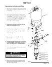
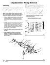
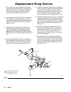
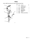
12. Lubricate the priming piston rod (18), then slide the
assembled intake valve (V) onto the rod, making
certain that the packing nut (15) goes on the rod
first. Push the valve assembly up the rod, stopping
before it reaches the intake valve housing (17).
See Fig. 14.
13. Hold the valve body (16) steady with a wrench
while using an adjustable wrench to tighten the
packing nut (15). See Fig. 14. Torque to 97–107
N.m (71–79 ft-lb). Use a rubber mallet on the
priming piston rod (18), to drive the valve assem-
bly up to the stop (VS).
14. The intake seat (37) is reversible. Inspect both
sides of the seat and install it with the best side
facing into the housing (17). Push it into the hous-
ing until it seats securely. Lubricate the seal (38*)
and install in the bevel around the bottom of the
seat. See Fig. 16.
04992
Fig. 14
1
Hold valve body (16) steady.
Torque packing nut (15) to
97–107 N.m (71–79 ft-lb).
1
17a, b, c
18
16
15
V
10
2
1