


190-00595-01 Rev. B
Garmin G1000 Pilot’s Guide for the Beechcraft A36/G36
17
SYSTEM OVERVIEW
SYSTEM
OVERVIEW
FLIGHT
INSTRUMENTS
EIS
AUDIO PANEL
& cNS
FLIGHT
MANAGEMENT
HAZARD
AVOIDANCE
AFCS
ADDITIONAL
FEATURES
APPENDICES INDEX
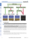
MAGNETOMETER FAILURE
If the magnetometer input fails, the AHRS transitions to one of the reversionary No-Magnetometer modes
and continues to output valid attitude information. However, if the aircraft is airborne, the heading output
on the PFD does become invalid (as indicated by a red “X”).
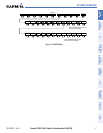
G1000 SYSTEM ANNUNCIATIONS
NOTE: For a detailed description of all annunciations and alerts, refer to Appendix A. Refer to the (AFM/
POH) for additional information regarding pilot responses to these annunciations.
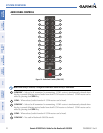
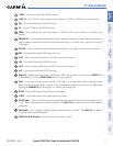
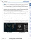
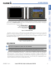
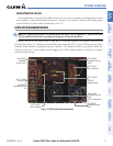
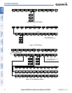
When an LRU or an LRU function fails, a large red “X” is typically displayed on windows associated with
the failed data (Figure 1-14 displays all possible flags and responsible LRUs). Upon G1000 power-up, certain
windows remain invalid as equipment begins to initialize. All windows should be operational within one
minute of power-up. If any window remains flagged, the G1000 system should be serviced by a Garmin-
authorized repair facility.
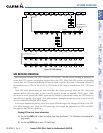
Figure 14 G1000 System Failure Annunciations
GDC 74A Air
Data Computer
GTX 33 Transponder
Or
GIA 63/63W
Integrated Avionics
Units
GDC 74A Air
Data Computer
GEA 71 Engine
Airframe Unit
Or
GIA 63/63W
Integrated Avionics
Unit
GIA 63/63W
Integrated Avionics
Units
GRS 77 AHRS
Or
GMU 44
Magnetometer
GIA 63/63W
Integrated Avionics
Units
GIA 63/63W
Integrated
Avionics Units