


31
32
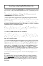
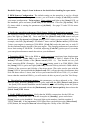
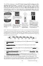
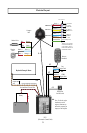
NMEA 0183 Connections
The Autopilot does not need to connect to a GPS for the autopilot to work, but if you want to use
waypoint steering you must connect to a GPS and set North see page 30. The Autopilot will accept
NMEA input from two GPS units and transmit NMEA to one receiving device. Only one of the GPS
inputs is used for steering control at a time. Selection of the controlling GPS is made through the
NMEA source selection [code 34] (see pages 19-22 for explanation of setup codes). The NMEA
output port transmits the NMEA sentence $APHDG at 4800 baud. The output refresh rate is selectable
via [code 49] from 0 to 10 Hz. The Autopilot requires the data sentences RMC and RMB to be on.
The NMEA conductors are in the cable stub at the base of the Compass Ball. (See Labels on Wires
for Identi cation) The wire color codes and signal names are shown in the wiring diagram below.
You must calibrate the compass ball and set North during Sea Trial of autopilot for it to work
correctly.
Note: If you are using Radar Overlay, you may need to adjust code 168 in order for your overlay to
line up correctly.
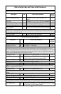
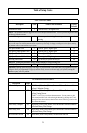
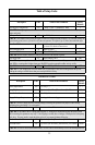
See pages 38-41 in the installation manual or go to www.tr-1autopilots.com (Manuals)for updates
of speci c brands of GPS wiring con gurations. Not all GPS brands and models are available.
TR-1 updates these regularly. The chart is a guide only and is to help you with your GPS connections
and should not be used as factual
information. Please check your GPS
manual for veri cation of NMEA 0183
connections on your application. This
is not a compatibility chart, but most all
GPS units are compatible with the
TR-1 Gladiator.
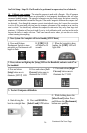
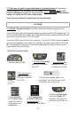
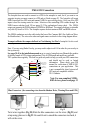
Twist wires together. (Fig 20) Slide the blue connectors over the wires (Fig 21) and
crimp using pliers as in Fig 22. Be careful not to smash the connectors too hard, it
will cut the wires.
Fig. 21
Blue Connectors (for connecting wires from the Shadow Drive, Warning Horn and GPS)
Fig. 20
Fig. 22
Note: For non-compliant NMEA
0183 devices, please read page 33
Compass
Ball
Red ( +)
Black (- )
Green (GND)
Yellow ( + )
White ( - )
Blue ( + )
Brown ( - )
NMEA Out
NMEA In # 1
NMEA In # 2
Chart Plotter
Radar Overlay
NMEA IN*
GPS #1
NMEA out*
{
{
{
}
}
}
GPS #2
NMEA
out*
Not normally
Used
Wire Connectors
( + )
( + )
( + )
( - )
( - )
( - )
To ECU #4 Connector
To Shadow Drive
and Warning Horn
Connectors
T
o ECU #4 Connector