16
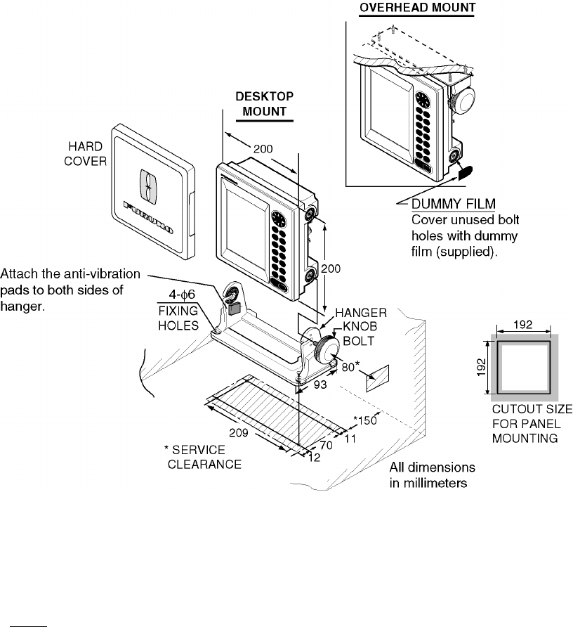
Figure 3-1 Mounting dimensions of display unit
3.2 Wiring
Connection of radar
1. Unfasten screws and three connector nuts (NMEA, POWER, DJ-1) from the rear cover of
the radar to detach it.
2. Place the rear cover on a workbench, out side up.
3. Using a slotted-head screwdriver and hammer, punch out the “hole cover” from the
location shown in Figure 3-2. Remove burrs from the hole with a fine file or sandpaper.
4. Insert MJ connector side of the MJ-XH connector (supplied) in the hole made at step 3
and fasten it with the connector nut (torque: 0.75-0.78 N•m). Tighten the connector nut by
hand until you feel slight resistance and then turn it an additional 45
° with a box wrench.
Note: Be sure the MJ-XH connector is free of foreign material before attaching it.
Watertight integrity cannot be guaranteed if foreign material (dust, etc.) is on the
connector when it is assembled.
5. Plug in the XH connector of the MJ-XH connector into J7 on the DU Board.
6. Insert NMEA, POWER and DJ-1 connectors. Tighten connector nut by hand until you feel
slight resistance and then turn it an additional 90
° (NMEA and POWER) or 45° (DJ-1)
with a box wrench.
7. Close the rear cover by using screws (
3X12) in the installation materials. (Be sure the
gasket is correctly positioned and there is no foreign material in the unit before closing
the cover.)
8. Connect signal cable between connector DJ-1 on the remote display and the MJ
connector (attached at step 4) on the radar.
9. Seal hole with silicone sealant or putty for waterproofing.


