


3. INSTALLATION
27
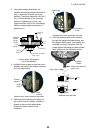
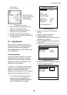
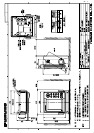
Display unit, rear view
3. Close the rear panel, making sure the
gasket is correctly positioned.
4. Plug in the connector of the external
buzzer to J6 on the DU Board.
5. Seal the hole with sealing compound.
6. Fix the buzzer to the location desired with
two tapping screws.
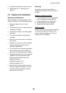
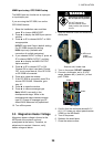
3.4 Adjustments
After you have installed the radar, do the
heading alignment and timing adjustment. If
you are connecting external equipment,
follow “NMEA port setup, GPS WAAS setup”
(for GP-320B) also.
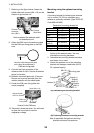
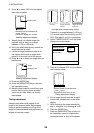
Heading alignment
You have mounted the antenna unit facing
straight ahead in the direction of the bow.
Therefore, a small but conspicuous target
dead ahead visually should appear on the
heading line (zero degrees).
In practice, you will probably observe some
small error on the display because of the
difficulty in achieving accurate initial
positioning of the antenna unit. The following
adjustment will compensate for this error.
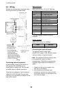
1. Turn on the power while pressing and
holding down the [MENU/ESC] key.
Continue pressing the [MENU/ESC] key
until the Installation menu appears.
SIMULATION OFF
TEST ...
LCD PATTERN ...
MEMORY CLEAR
NMEA PORT : IN/OUT
NMEA OUTPUT : OFF
GPS WAAS : OFF
GOTO RADAR SETUP...
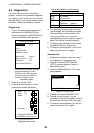
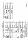
INSTALLATION MENU
Installation menu
2. Press ▼ to choose GOTO RADAR
SETUP.
3. Press ►. Power is then reset.
4. Wait one minute, press the
[POWER/BRILL] key and then press the
[MODE] key to transmit.
5. Press the [MENU/ESC] key to show the
User menu.
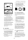
6. Press ► to show the Radar Setup menu.
RADAR SETUP
HEADING ADJUST
TIMING ADJUST
SET ON TIME : 000000h
SET TX TIME : 000000h
[MENU/ESC]: Exit.
Radar setup menu
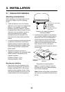
7. HEADING ADJUST is selected; press ►
to show the options window.
RADAR SETUP
HEADING ADJUST
TIMING ADJUST
SET ON TIME : 000000h
SET TX TIME : 000000h
[MENU/ESC]: Exit.
: YES
: NO
Radar setup menu (heading adjust)