


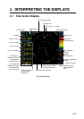

2. INTERPRETING THE DISPLAYS
2-4
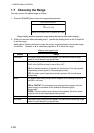
Item Description
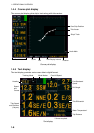
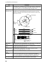
Heading line
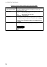
The heading line is a dashed line which shows ship’s heading. It extends from
ship’s position (center of vector display) to the edge of the vector display. The
line can be turned on or off with HEADING LINE in the DISP1 menu.
Tide vectors may be turned on or off with LAYER 1, LAYER 2 and LAYER 3 in
the DISP1 menu. The tide differential may be also be turned on or off with
TIDE DIFF in the DISP1 menu. Note that if vectors overlap, the vector of the
highest layer is shown.
(4)
Heading Line
N
W
E
S
NW
NE
SW
SE
(1)
(2)
(3)
Tide Vectors
(5)
Tide
Differential
Vectors
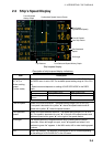
(1)
(2)
(3)
Layer 1
Yellow
Yellow
. . . .
Layer 2
Purple
Purple
. . . .
Layer 3
Light-blue
Light-blue
. . . .
Tide/tide
differential vector
(4)
(5)
2 1
2
3
PurpleLight-bluePurpleLight-blue
Purple
Light-blue
Purple
Yellow
Reference
Layer
(Left half)
Measuring Layer
(Right half)
. . . .
. . . .
Purple
Yellow Purple Yellow
Ship’s speed
vector
The ship’s speed vector may be shown on the vector display. This vector can
be turned on or off with SHIP SPD VCTR in the DISP1 menu.
Electronic bearing
scale
The electronic bearing scale shows bearing. If a heading sensor is connected
the scale rotates with ship’s movement.
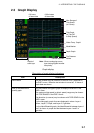
Tide speed range Tide speed range, as selected with TIDE RANGE in the DISP1 menu,
appears at the top right-hand side on the screen.
Tide average
setting
The value set with TIDE AVERAGE in the MENU 1 menu is shown.
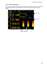
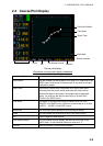
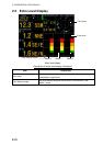
Echo level The echo level display shows echo level for the three sounding beams in
colors or graph depending on the setting of DISP MODE in the DISP2 menu.
You can turn the display on or off with ECHO LEVEL in the DISP2 menu.
Echo display range The value set with ECHO RANGE in the MENU 1 menu is shown.