


303-06-13 303-06-13Starting System
DIAGNOSIS AND TESTING (Continued)
PINPOINT TEST B: THE ENGINE DOES NOT CRANK AND THE RELAY DOES CLICK (Continued)
Test Step Result / Action to Take
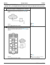
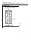
B2 CHECK THE VOLTAGE TO THE STARTER MOTOR SOLENOID
• Measure the voltage between starter motor solenoid positive
terminal and ground.
Yes
GO to B3.
No
REPAIR circuit 2037 (RD) for an open.
• Is the voltage 10 volts or greater? TEST the system for normal operation.
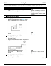
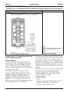
B3 MANUALLY JUMP THE STARTER MOTOR
• Connect one end of a fused (15A) jumper wire to the positive
terminal of the battery and touch the other end to the starter
solenoid S-terminal.
Yes
GO to B4.
No
INSTALL a new starter motor. REFER to
Starter Motor — 4.0L SOHC or Starter
Motor — 4.6L (3V) in this section. TEST
• Does the starter solenoid engage? the system for normal operation.
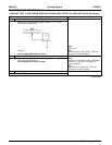
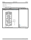
B4 TEST THE STARTER MOTOR RELAY
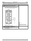
• Carry out the relay component test on the starter motor relay.
Yes
Refer to Wiring Diagrams Cell 149 for component testing. REPAIR circuit 113 (YE/LB) for an open.
• Does the starter motor relay test good? TEST the system for normal operation.
No
INSTALL a new starter motor relay. TEST
the system for normal operation.
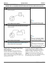
Pinpoint Test C: The Engine Cranks Slowly
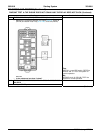
For automatic transmission equipped vehicles,
voltage is supplied from the SJB to the digital
Normal Operation
transmission range (TR) sensor through circuit 32
In normal operation, voltage from the bussed
(RD/LB). In PARK or NEUTRAL, voltage is
electrical center (BEC) is supplied to the ignition
supplied from the TR sensor through circuit 33
switch through circuit 1050 (LG/PK). When the
(WH/PK) to the starter relay coil located in the
ignition switch is placed in the START position,
BEC. The starter relay coil is supplied ground from
voltage is supplied through circuit 1522 (DG) to the
the PCM through circuit 1419 (LG/YE).
smart junction box (SJB).
2005 Mustang, 12/2004