


303-06-15 303-06-15Starting System
DIAGNOSIS AND TESTING (Continued)
Possible Causes
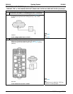
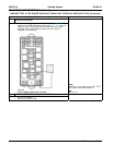
For manual transmission equipped vehicles, voltage
from the SJB is supplied to the clutch pedal position
• Starter motor mounting
switch (CPP) through circuit 32 (RD/LB). When the
• Starter motor mounting bolts
clutch pedal is depressed, voltage is supplied from
• Starter motor drive
the CPP to the starter relay coil located in the BEC
through circuit 32 (RD/LB). The starter relay coil is
• Flywheel or flexplate ring gear
supplied ground from the PCM through circuit 1419
• Starter motor
(LG/YE).
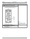
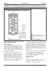
When the starter relay is energized, voltage supplied
to the relay switch is sent to the starter motor
solenoid through circuit 113 (YE/LB). Battery
voltage is supplied to the starter motor through
circuit 2037 (RD) at all times.
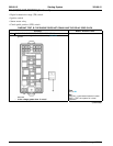
PINPOINT TEST D: UNUSUAL STARTER NOISE
Test Step Result / Action to Take
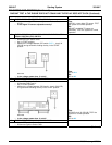
D1 CHECK THE STARTER MOTOR MOUNTING
• Inspect the starter motor mounting for cracks.
Yes
• Check the starter motor mounting bolts for looseness. GO to D2.
• Is the starter motor mounted correctly?
No
REINSTALL the starter motor correctly.
REFER to Starter Motor — 4.0L SOHC or
Starter Motor — 4.6L (3V) in this section.
D2 INSPECT THE STARTER MOTOR
• Remove the starter motor. Refer to Starter Motor — 4.0L SOHC
Yes
or Starter Motor — 4.6L (3V) in this section. INSTALL a new starter motor. TEST the
• Inspect the starter motor for damage. system for normal operation.
• Is the starter motor damaged?
No
CHECK the starter drive. REFER to
Component Tests, Starter Drive Test in
this section. INSTALL a new starter motor.
TEST the system for normal operation.
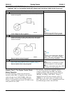
Component Tests
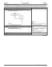
3. Connect the SABRE tester to the vehicle using
the amperage lead clipped around the positive
Starter Motor — Load Test
battery cable.
WARNING: When servicing the starter
4. Measure the amperage of the starter motor
motor or carrying out other underhood work in
while activating the starting system.
the vicinity of the starter motor, be aware that
5. A correctly operating starter motor will draw
the heavy gauge battery input lead at the starter
from 130 to 190 amps of current.
solenoid is ‘‘electrically hot’’ at all times.
Voltage Drop Tests
CAUTION: A protective cap or boot is
The following test procedures will be carried out
provided over the battery input terminal on all
with the starter motor on the vehicle.
car lines and must be installed after repair. Be
sure to disconnect the battery ground cable
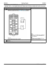
Motor Feed Circuit
before repairing the starter motor.
NOTE: Make all multimeter connections at the
1. Before carrying out this test inspection, check
component terminal rather than the cable or wiring
the battery to determine its state of charge.
terminal.
Carry out a load test of the battery using the
1. Disconnect the ignition coil connector from the
Starter, Alternator, Battery, Regulator and
ignition coil.
Electrical Tester (SABRE). Refer to Section
414-00 for the test procedure.
2. Connect a remote starter switch between the
starter solenoid S-terminal and the battery
2. Disconnect the ignition coil connector from the
positive (+) post.
ignition coil.
2005 Mustang, 12/2004