


303-06-7 303-06-7Starting System
DIAGNOSIS AND TESTING (Continued)
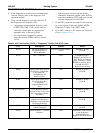
PINPOINT TEST A: THE ENGINE DOES NOT CRANK AND THE RELAY DOES NOT CLICK (Continued)
Test Step Result / Action to Take
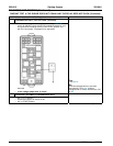
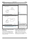
A6 CHECK DIGITAL TR SENSOR ADJUSTMENT
• Carry out the digital TR sensor adjustment. Refer to Section
Yes
307-01. INSTALL a new digital TR sensor. TEST
• Is the digital TR sensor adjusted correctly? the system for normal operation.
No
ADJUST the digital TR sensor as
necessary. TEST the system for normal
operation.
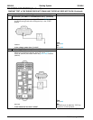
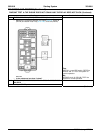
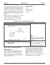
A7 CHECK CIRCUIT 32 (RD/LB) FOR VOLTAGE AT THE CLUTCH
PEDAL POSITION (CPP) SWITCH
• Key in OFF position.
• Disconnect: CPP Switch C257.
• Key in START position.
• Measure the voltage between CPP switch C257-1, circuit 32
(RD/LB) and ground while holding the key in the START
position.
Yes
GO to A11.
No
• Is the voltage greater than 10 volts? GO to A8.
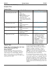
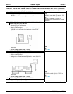
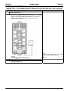
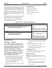
A8 CHECK CIRCUIT 1522 (DG) FOR AN OPEN
• Key in OFF position.
• Disconnect: SJB Fuse 21.
• Key in START position.
• Measure the voltage between SJB fuse 21, circuit 1522 (DG)
and ground while holding the key in the START position.
Yes
REPAIR circuit 32 (RD/LB). TEST the
system for normal operation.
No
• Is the voltage greater than 10 volts? GO to A9.
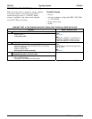
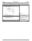
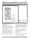
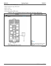
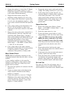
A9 CHECK CIRCUIT 1050 (LG/PK) FOR VOLTAGE
• Key in OFF position.
• Disconnect: Ignition Switch C250.
(Continued)
2005 Mustang, 12/2004