


P/N: 4FM020-010
© 2003 Vortech Engineering, LLC
All Rights Reserved. Intl. Copr. Secured
20OCT03
v3.1 4.6/5.4Exped/Nav(4FM v3.1)
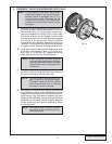
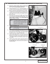
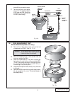
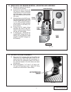
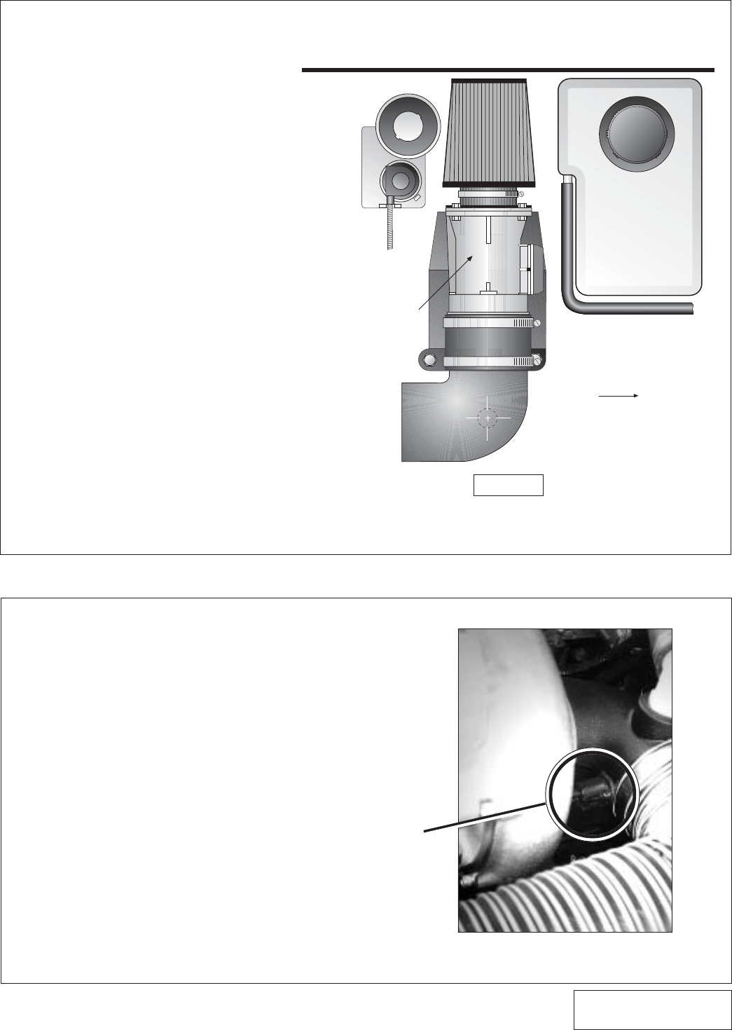
13. MASS AIR FLOW SENSOR REMOVAL, MOUNTING AND ASSEMBLY
17
A. Separate the mass air flow sensor
from the air inlet canister.
B. Assemble the mass air sensor and
the mass air sensor mounting
bracket with the 1/4-20 x 3/4" bolts,
nuts and washers. Mount the air
filter to the bracket and secure the
#60 clamp.
C. Using the factory air inlet filter can-
ister mounting location, secure the
mass air bracket with the 5/16-18
x 1-1/2” bolts, nuts and washers;
use the large 5/16 fender washers
on the bottom of the factory rub-
ber grommets.
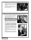
D. Connect the 90° plastic elbow
equipped with the 3/4” barb 90°,
to the 3-1/2 silicone sleeve. Secure
with the #56 hose clamps.
E. 5.4 Models only - Wire/Install the
supplied MAF Voltage Limiter As-
sembly. Use the instruction sheet
supplied in the MAF Voltage Lim-
iter Assembly.
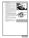
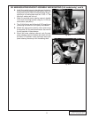
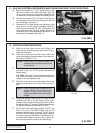
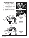
14. AIR INLET/BYPASS ASSEMBLY
A. Place the 3-1/2” silicone sleeve and the #56 hose
clamps onto the supercharger inlet. Install the 90°
plastic inlet elbow. Secure the #56 hose clamps. In-
sert the factory air temperature sensor into the rub-
ber grommet located on the inlet elbow and attach
the connector.
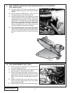
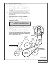
B. Attach the supplied 1” x 5” hose 1" x 9" hose -4.6L,
5.4L and #16 hose clamp to the 1” plastic 90° fitting
installed on the inlet elbow. Secure clamp.
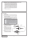
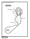
TOP VIEW
INNER FENDERWELL
MASS AIR
FLOW
SENSOR
CRUISE
CONTROL
COOLANT
RESERVOIR
FRONT
Fig. 13-a
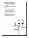
AIR TEMPERATURE
SENSOR
Fig. 14-a