


P/N: 4FM020-010
© 2003 Vortech Engineering, LLC
All Rights Reserved. Intl. Copr. Secured
20OCT03
v3.1 4.6/5.4Exped/Nav(4FM v3.1)
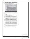
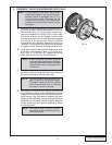
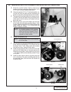
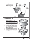
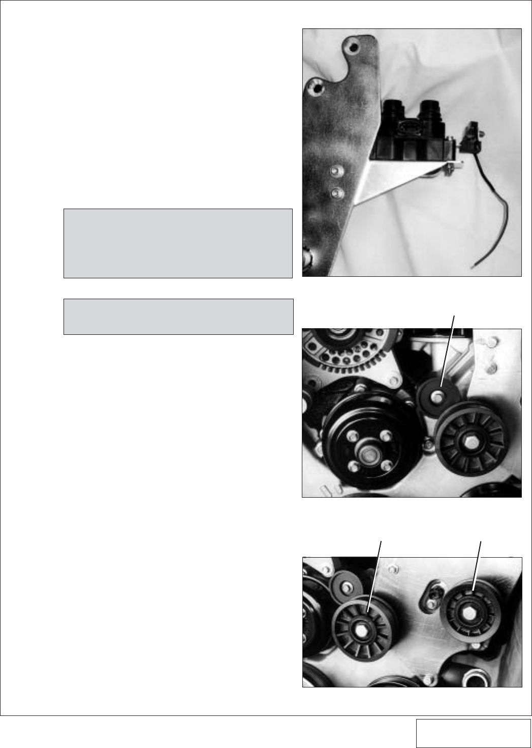
A. Attach the supplied power steering reservoir/coil
bracket to the main mounting plate using the 1/4-20
x 3/4” bolts, nuts and washers (see photo).
B. Using the supplied 10-24 x 2” bolts and washers, se-
cure the coil and the radio ignition interference ca-
pacitor to the power steering reservoir/coil bracket.
C. To prepare the mounting location for the main mount-
ing plate, remove the three factory stud/bolts previ-
ously used to hold the factory coil bracket to the en-
gine front cover.
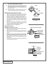
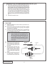
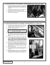
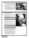
D. Remove the front cover bolt located near the lower
driver's side of the alternator mounting flange. In this
location, install the supplied 2.25” idler pulley and idler
spacer using the 10mm x 1.50 x 85mm bolt and
washer. Torque to 40 in/lbs.
E. Reinstall the accessory belt.
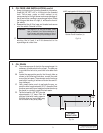
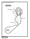
F. With the main mounting plate positioned on the front
cover, start the supplied 8mm-1.25 x 25mm bolt and
the three 10mm -1.50 x 85mm bolts with washers
into the front cover. Torque all bolts evenly.
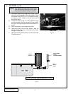
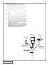
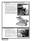
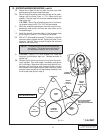
G. Install the large smooth idler on the inner most idler
stand and the ribbed idler on the outer stand of the
Vortech mounting plate. Secure both with the 12mm
- 1.75 x 20mm bolts and dust shields provided. Torque
to 45 ft/lbs.
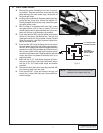
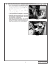
H. Install the cam position sensor plug and secure the
wire to the face of the main mounting plate with the
provided adel clamp. Use the lower coil bracket bolt
to secure clamp.
8A. MAIN MOUNTING PLATE ASSEMBLY AND MOUNTING (4.6L models only)
9
NOTE: In a limited number of 4.6L engines,
the main bracket holes and single idler
pulley hole are 8mm instead of 10mm.
Four 8mm shoulder bolts have been
supplied for these models.
NOTE: The use of blue Loctite is recommended
for all idler bolts.
2.25" IDLER PULLEY
SMOOTH IDLER RIBBED IDLER
Fig. 8A-b
Fig. 8A-a
Fig. 8A-c