P/N: 4FM020-010
© 2003 Vortech Engineering, LLC
All Rights Reserved. Intl. Copr. Secured
20OCT03
v3.1 4.6/5.4Exped/Nav(4FM v3.1)
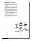
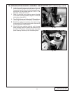
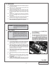
10. FUEL MANAGEMENT UNIT (FMU)
A. Using a spring lock disconnect tool, disconnect the
fuel return line at the fuel rail.
B. Connect the FMU inlet hose to the fuel rail. Route the
fuel line to the 90° brass fitting on the FMU.
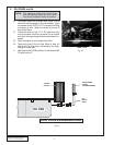
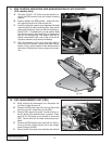
C. Position FMU against the upper firewall directly un-
der the plastic wire harness cover as shown. Mark
and drill two #30 holes on the firewall to mount the
FMU. Secure with the #8 sheet metal screws pro-
vided.
D. Connect the FMU outlet hose to the fuel line that re-
turns to the tank. Route the fuel line to the straight
brass fitting on the FMU.
E. Secure the fuel lines away from abrasion and exhaust
Fig. 10-a
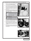
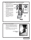
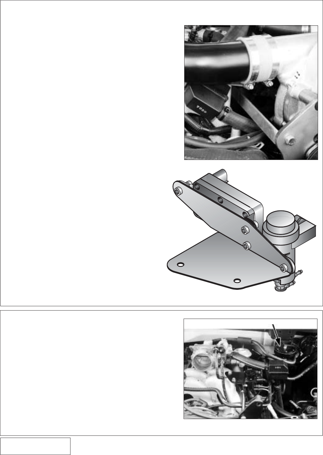
9. EGR CONTROL MOUNTING AND MAIN MOUNTING PLATE SUPPORT
(4.6L models only)
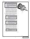
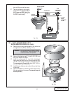
A. Using the #10-24 x 1/2” bolts, nuts and washers, re-
mount the EGR controls onto the Vortech mounting
bracket.
B. Directly beneath the EGR bracket, locate the 6mm
bolt securing the fuel rail. Remove the bolt.
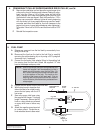
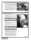
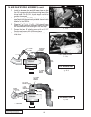
C. Install the supplied support strap between the intake
manifold and the main mounting plate. Secure both
ends using the factory 6mm fuel rail bolt and the sup-
plied 3/8-16 x 1" hexhead bolt, nut and washer. Make
sure that the strap is not sandwiched in between the
fuel rail and the manifold. The support must be at-
tached underneath the bolt, and on top of the rail tab.
Improper assembly may cause fuel leakage.
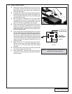
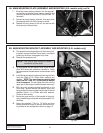
D. With the two factory 6mm bolts previously used to
mount the EGR controls, remount the new EGR as-
sembly in the original location on the intake manifold
and secure. Reconnect all factory hoses and connec-
tors.
12
Fig. 9-a
Fig. 9-b


