


P/N: 4FM020-010
© 2003 Vortech Engineering, LLC
All Rights Reserved. Intl. Copr. Secured
20OCT03
v3.1 4.6/5.4Exped/Nav(4FM v3.1)
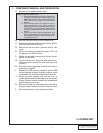
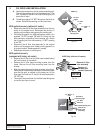
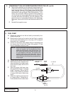
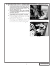
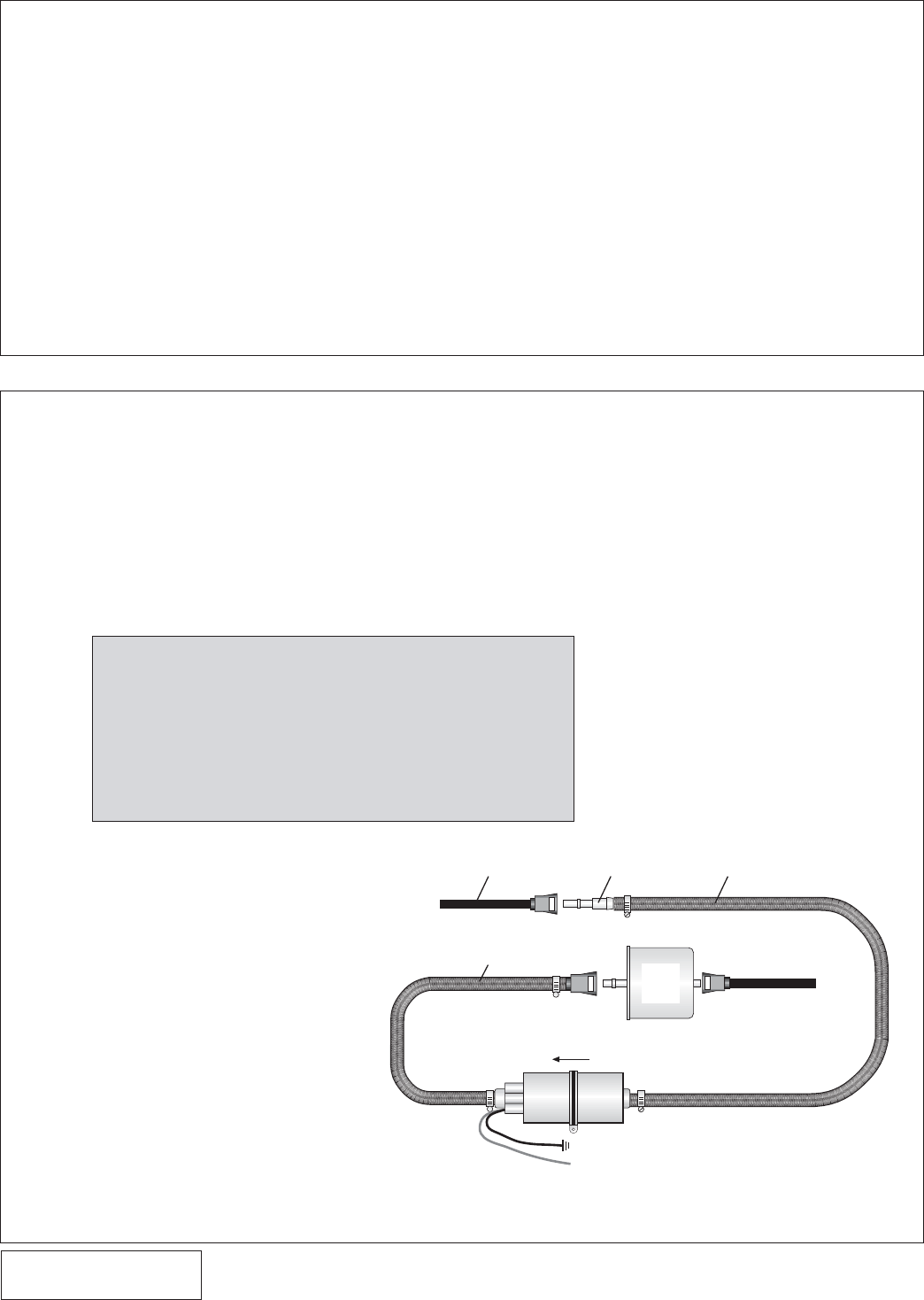
5. FUEL PUMP
A. Release any pressure from the fuel tank by momentarily loos-
ening the filler cap.
B. Disconnect the line from the tank to the fuel filter by carefully
removing the white retaining clip or by using a 3/8” springlock
disconnect tool, if equipped.
C. Connect the fuel pump inlet adapter fitting to the existing fuel
line coming from the fuel tank. Attach the supplied 1/2" inlet
hose to the adapter and pump inlet.
D. Connect the fuel pump outlet to the filter inlet.
6
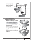
5/16” HOSE
EXISTING FEED LINE
FROM TANK
(-) GROUND BLACK WIRE
CONNECT TO
(+) RELAY
TERMINAL (87)
STOCK
FUEL
FILTER
ADAPTER
FITTING
1/2” FUEL LINE
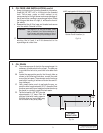
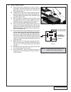
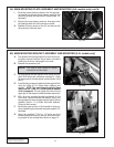
4. CRANKSHAFT PULLEY/SUPERCHARGER DRIVE PULLEY, cont'd.
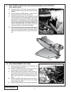
NOTE: Due to the various fuel tank configurations and
frame rail lengths it will be necessary to find a
good mounting location near the fuel filter. Do
NOT mount the fuel pump close to exhaust heat
or to the bottom of the cab. The inside or the
outside of the frame rail will work well. Prior to
securing the fuel pump ensure the fuel lines will
not be kinked or pinched and are protected from
sharp edges.
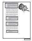
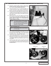
E. Remove the installation tool and place the supercharger drive
pulley on the front of the harmonic balancer. Feeling for align-
ment, start the 12mm x 1.50 x 65mm center bolt with thick
factory washer and rotate the supercharger drive pulley until
the three bolt holes are aligned. Start the three 8mm x 1.25 x
25mm cap screws with washers, tighten all evenly beginning
with the center bolt (some applications may need two wash-
ers under each 8mm bolt head for thru-bolt clearance to the
engine front cover. Inspect behind balancer when tightening).
Torque the 12mm bolt to 80 ft/lbs and the 8mm bolts to 25 ft/
lbs.
F. Reinstall the inspection cover.
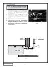
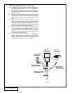
E. With the fuel pump in a position that
allows the lines to be routed loosely,
secure the fuel pump with the #12
hex screw.
F. Secure the pump inlet hose using
the supplied #8 clamps. Trim hose
length if necessary. Ensure that NO
kinks or sharp bends are allowed
on pump inlet hose or failure may
result.
G. Attach the negative pump terminal
to a clean ground. Scrape the ve-
hicle undercoat down to bare metal.
Fig. 5-a