


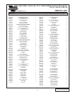
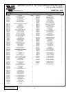
P/N: 4FM020-010
© 2003 Vortech Engineering, LLC
All Rights Reserved. Intl. Copr. Secured
20OCT03
v3.1 4.6/5.4Exped/Nav(4FM v3.1)
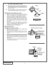
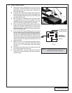
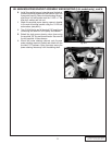
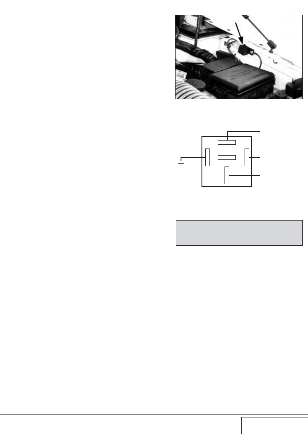
6. FUEL PUMP RELAY
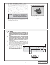
A. Remove the power distribution box from its mount-
ing bracket. Remove the bottom cover and the side
panel exposing the main power lugs, the bottom of
the fuses and relays.
B. Looking at the underside of the power distribution box,
locate the fuel pump relay (should be labeled #4).
Directly beneath the fuel pump relay, locate the green
wire with yellow stripe.
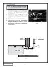
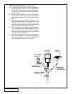
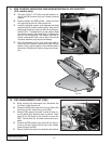
C. With the help of an assistant and a test light, check
the green/yellow wire for key-on power, this wire
should show power for approximately two to four sec-
onds with the key in the accessory on position.
D. From relay terminal #85 route the yellow wire into the
bottom of the power distribution box. Tap into the
green/yellow wire with the provided wire tap. Double
check the wire with a test light to ensure a good con-
nection has been made.
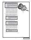
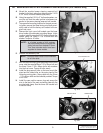
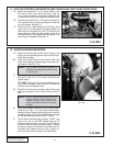
E. From terminal #30 route the heavy red wire to one of
the main power lugs at the side of the power distribu-
tion box. With the supplied male and female solderless
connectors, install the fuse holder and 20 amp fuse in
this wire and check with a test light to ensure a good
connection has been made. Close the bottom and side
covers and return the power distribution box to its
original position.
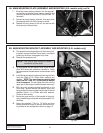
F. Mark and drill a 1/8” hole above the power distribu-
tion box on the driver's side inner fenderwell, secure
with the #12 x 3/4" sheet metal screw and washer
provided.
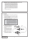
G. Connect the short black wire from relay terminal #86
to a secure ground free from paint.
H. From terminal #87, route and connect the long red
wire to the (+) side of the fuel pump. Secure with pro-
vided tie wraps.
7
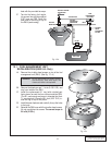
(+) T-REX FUEL PUMP
(LONGEST RED WIRE)
TO #4 RELAY -
GREEN WIRE WITH
YELLOW STRIPE
12 VOLT (+)
30
86
87
85
GROUND
87A
RELAY
NOTE: Double check that all wires are con-
nected to their proper relay lug.
Fig. 6-b
Fig. 6-a