


Data sheet
Copyright © Emerson Process Management. The information in this document is subject to change without notice.
Updated data sheets can be obtained from our website www.El-O-Matic.com or from your nearest Valve Automation Center USA: +1 813 319 0266 Europe: +31 74 256 10 10 Asia-Pacific: +65 6501 4600
www.El-O-matic.com
Sheet No.:
Date: May 2011
A1.103.200 Rev. B
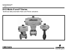
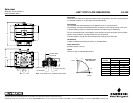
DRIVE INSERTS FOR EL-O-MATIC ACTUATORS E
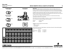
Description
Most of the El-O-Matic actuators are fitted with drive inserts. This enables actuators to be
directly mounted onto suitable valves and eliminates the need for a bracket and coupling type
mounting kit. The use of direct mounts significantly cuts the cost of the valve/actuator assembly.
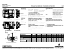
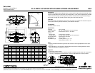
Standard actuators are fitted with square drive inserts in accordance with ISO 5211 (or DIN
3337), but a wide variety of other inserts are also available. Special inserts may have oversize or
undersize squares, double-D and shaft key way forms.
Drive inserts can be supplied on factory built actuators or as loose items and are easily
replaceable at distributor or end user level.
Where direct mounts are not possible, for instance on valves with exposed grand packing, the
use of inserts often simplifies the design of the mounting kit.
Material : Aluminum alloy
Finish : Anodized
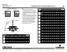
The following actuator types do not have inserts.
- E12,
- P2500 and P4000
- 180° actuators
These actuators have inner square directly in the bottom of the pinion. See the following data
sheets for more information :
E12 ISO5211 A1.103.102
P2500/P4000 ISO 5211 A1.103.106
180° ISO 5211 A1.203.011
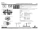
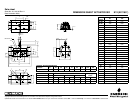
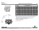
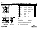
Ø P2
Ø P1
M1
M2
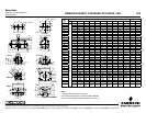
Standard available
insert shapes
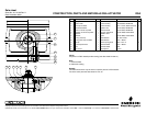
Insert mounting
acc. ISO 5211
Optional available
insert shapes
sq Max.
D Max.
D Max.
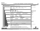
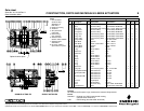
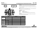
Standard inserts with inner-square-dimensions per actuator type
E25 E40 / E65 E100 E150 E200 E350 E600 E950 E1600
0.433 0.551 0.748 0.866 0.866 1.063 1.063 1.417 1.811
Optional insert dimensions
0.354 0.394 0.472 0.551 0.551 0.551 0.551 0.866
0.394 0.472 0.551 0.630 0.630 0.630 0.630
0.63 0.669 0.669 0.669 0.669
0.748 0.748 0.748 0.748
0.945 0.945 0.866 0.866
1.063 1.063 0.945 0.945
Maximum insert dimensions
M1 1.36 1.36 1.36 1.97 1.97 1.97 2.05 2.52 3.23
M2 - - 1.06 1.46 1.46 1.46 - - -
P1 0.71 0.71 0.91 1.26 1.26 1.26 1.44 1.91 2.38
P2 - - 0.99 1.43 1.43 1.43 - - -
SQ max. 0.630 0.630 0.748 1.063 1.063 1.063 1.063 1.417 1.811
D max. 0.827 0.827 0.929 1.323 1.323 1.323 1.323 1.772 2.362