


12 DOC,F20,EDN Rev.: -
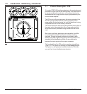
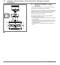
3.1 Mechanical Installation - Linear Ac-
tuators
The mounting set is used for mounting POSIFLEX positioners
on linear actuator which have mountings in accordance with
DIN IEC 534-6. All parts are made from stainless steel. The
mounting sets contain two different levers for different stroke
ranges:
1. Stroke 10 - 65 mm
2. Stroke 65 - 100 mm
Mounting is possible for actuators with pillars, by using the
bracket (7) with the U-bolt (8). Or for actuators with a cast pad,
by direct fitting using the screw M8x20 (16) with washer M8
(17). The linear moving of actuator has to be converted into a
rotation of the shaft of positioner. The distance ”A” between
coupling bolt (6) and shaft of positioner is set with reference to
the table below. This distance is a function of stroke S. Pre-
setting the linkage with this distance ”A” enables the best range
setting to be achieved with only a small adjustment on the
positioners’ range setting. A spring (3); (5) in lever (2); (4)
eliminates play in the linkage.
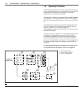
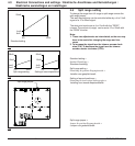
3.0 Installation - Linear Actuators / Einbau - Hubantriebe / Montage - lineaire aandrijvingen
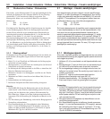
9;11
7
8
15
12;18
A
6
12;14
10;13
2;3 / 4;5
1
30
3.1
3.2
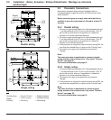
l = long lever (4)
k = short lever (2)
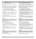
reference to the table 3.2.
5. Fix coupling bolt with nut M6 (10).
6. Adjust positioner (zero, range, amplification).
7. Change setting of zero and range as required.
Note:
1. POSIFLEX positioners for linear applications are
adjusted for an angle of 40° as standard (see table
above). For different strokes i.e. 10mm or 100 mm
(other angle!) reset zero and range adjustment of
F20.
2. Several parts, standard parts e.g., of mounting kit
are already pre-assembled for ease of assembly.
3. Using only one lever is possible in applications of
F20 if the relation of stroke and distance ”A” is not
more than 1,0. To use this type of assembly,
please also order coupling bolt ES (Part number
6.003618).
l = langer Hebel (4)
k = kurzer Hebel (2)
l = lange hefboom (4)
k = korte hefboom (2)
3.3
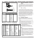
No. Qty Description
Umschreibung
Omschrijving
Norm
1 1 Carrier bracket
Mitnehmerblech
Meeneembeugel
2 1 Lever, short
Heb el-kurz
Hefboom kort
3 1 Spring,short
Feder-kurz
Veer kort
4 1 Lever,long
Heb el-lan g
Hefboom lang
51Spring,long
Feder-lang
Hefboom kort
6 1 Couplingbolt
Mitn eh me r
Meeneembout
7 1 Bracket for postioner
Montagewinkel
Montagebeugel
82U-bolt
Spannbügel
Spanbeugel
94NutM8
Mu tter M8
Moer M8
DIN 934
10 1 Nut M6
Mu tter M6
Moer M6
DIN 439
11 4 Lockwasher B8
FederringB8
Ring B8
DIN 127
12 3 Lockwasher B6
FederringB6
Ring B6
DIN 127
13 1 Disk A6,4
Scheibe A6,4
Schijf A6,4
DIN9021
14 3 ScrewM6x10
Schraube M6x10
Schroef M6x10
DIN 933
15 1 ScrewM3x10
Schraube M3x10
Schroef M3x10
DIN 912
16 1 ScrewM8x20
Schraube M8x20
Schroef M8x20
DIN 933
17 1 Lockwasher B8
Federrin
g
B8
Rin
g
B8
DIN 917
18 2 ScrewM6x12
Schraube M6x12
Schroef M6x12
DIN 933
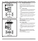
S (in mm.) A (in mm.)
∝= 24,5° ∝= 40° ∝ = 49°
10 23 (k)
16 22 (k)
20 27 (k)
30 41 (k)
32 44 (k)
50 68 (k)
55 75 (k)
65 89 (k),(l)
75 103 (l)
80 110 (l)
100 110 (l)
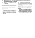
3.1.1 Installation sequence
The following installation sequence is for a positioner with a
direct action (increasing signal opens the valve with rising
spindle.)
1. Insert lever (2); (4) at end of positioner shaft and fix it with
screw.
2. Check the standard interface of actuator and mount bracket
(7) at left side of actuator - at pillar or casting pad.
3. Choose the position of bracket (7) where lever (2); (4) is in a
horizontal position and the actuator is in mid stroke.
4. Position the coupling bolt (6) for a correct distance ”A”, with