


1051 & 1052 H & J
Instruction Manual
Form 5587
November 2006
9
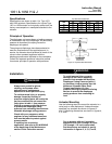
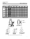
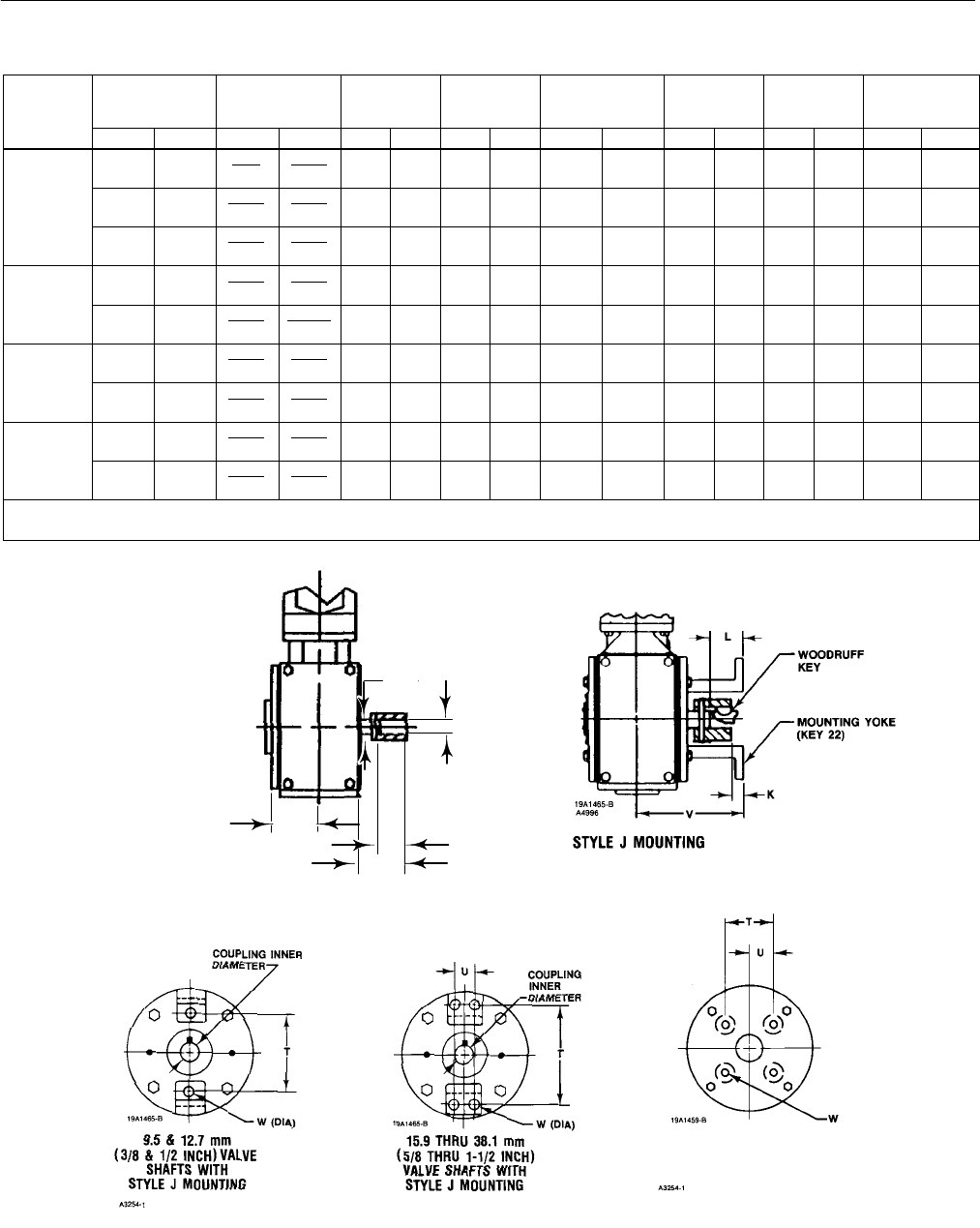
Table 6. Style J Mounting Dimensions
ACTUATOR
SIZE 1051 &
1052
VALVE SHAFT
DIAMETER
COUPLING
(1)
INNER
DIAMETER
V L
(2)
K T U W
1052
mm Inch mm Inch mm Inch mm Inch mm Inch mm Inch mm Inch mm Inch
9.5 3/8
9.53
9.58
0.375
0.377
137 5.38 39.6 1.56 15.7 0.62 117 4.62 - - - - - - 11.2 0.44
40
12.7 1/2
12.70
12.75
0.500
0.502
137 5.38 39.6 1.56 15.7 0.62 117 4.62 - - - - - - 11.2 0.44
15.9 5/8
15.90
15.95
0.626
0.628
160 6.31 49.3 1.94 25.4 1.00 146 5.75 31.8 1.25 11.2 0.44
40&60
19.1 3/4
19.05
19.10
0.750
0.752
160 6.31 47.8 1.88 20.6 0.81 146 5.75 31.8 1.25 11.2 0.44
40 & 60
25.4 1
25.43
25.48
1.0010
1.0025
160 6.31 47.8 1.88 17.5 0.69 146 5.75 31.8 1.25 11.2 0.44
60&70
(3)
31.8 1-1/4
31.75
31.80
1.250
1.252
148 5.81 68.3 2.69 30.2 1.19 210 8.25 50.8 2.00 17.5 0.69
60 & 70
(3)
38.1 1-1/2
38.13
38.18
1.501
1.503
148 5.81 68.3 2.69 23.9 0.94 210 8.25 50.8 2.00 17.5 0.69
60&70
(3)
50.8
1-3/4
& 2
44.45
44.50
1.750
1.752
123 4.84 69.9 2.75 - - - - - - 88.9 3.50 44.5 1.75
1/2-13
UNC
1/2-13
UNC
60 & 70
(3)
50.8 2
50.83
50.90
2.001
2.004
123 4.84 69.9 2.75 - - - - - - 88.9 3.50 44.5 1.75
1/2-13
UNC
1/2-13
UNC
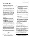
1. Tolerance for the Coupling Inner diameter is indicated by showing maximum and minimum dimensions.
2. The L dimension is the matchline to the end of the actuator shaft.
3. Size 70 is only available for the Type 1052.
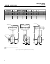
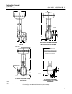
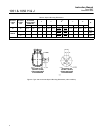
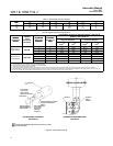
Figure 7. Type 1051 and 1052 Style J Mounting Dimensions (refer to table 6)
Y
Sj
L
V
K
19A1461-G
STYLE J MOUNTING
44.5 AND 50.8 mm (1Ć3/4 AND 2ĆINCH)
9.5 AND 38.1 mm (5/8 AND 1Ć1/2ĆINCH)
44.5 AND 50.8 mm (1Ć3/4 AND 2ĆINCH)
KEYED EQUIPMENT SHAFTS WITH
STYLE J MOUNTING