


1051 & 1052 H & J
Instruction Manual
Form 5587
November 2006
4
Specifications
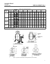
Specifications are shown in table 1 for Type 1051
and 1052 actuators. Specifications for a given Type
1051 or 1052 actuator as it originally comes from the
factory are stamped on a nameplate attached to the
actuator.
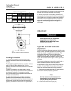
Principle of Operation
The diaphragm rod moves down as loading pressure
is increased on top of the diaphragm. As the loading
pressure is decreased, the spring forces the
diaphragm rod upward.
The spring and diaphragm have been selected to
meet the requirements of the application and, in
service, the actuator should produce full travel of the
valve or other operated equipment with the
diaphragm pressure as indicated on the nameplate.
Consult the separate positioner instruction manual
for actuator principle of operation with positioner.
Installation
WARNING
Always wear protective gloves,
clothing, and eyewear when
performing any maintenance
operations to avoid personal injury.
To avoid personal injury or property
damage caused by bursting of
pressure retaining parts, be certain the
service conditions do not exceed the
limits given in table 1. Use pressure
limiting or pressure relieving devices
to prevent the diaphragm sizing
pressure from exceeding the maximum
allowable diaphragm sizing pressure.
Check with your process or safety
engineer for any additional measures
that must be taken to protect against
process media.
If installing into an existing
application, also refer to the WARNING
at the beginning of the Maintenance
section in this instruction manual.
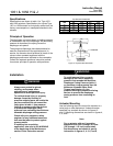
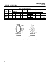
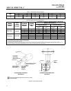
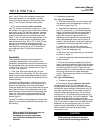
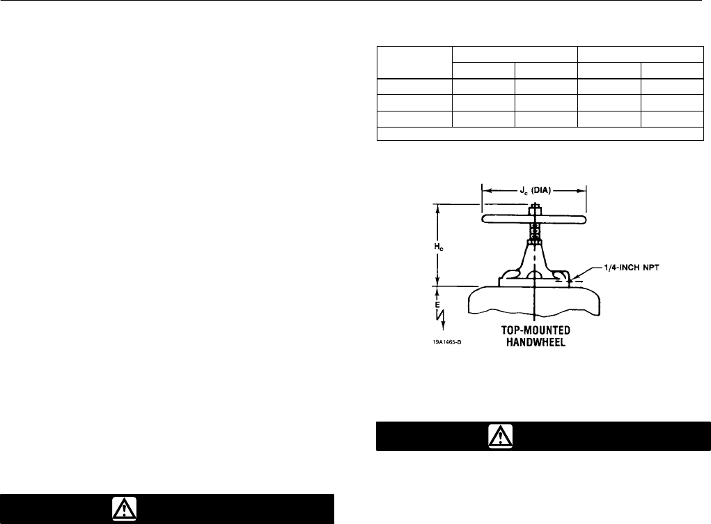
Top Mounted Handwheel
ACTUATOR
H
C
J
C
ACTUATOR
SIZE
mm Inch mm Inch
40 281 11.06 356 14.00
60 359 14.12 432 17.00
70
(1)
335 13.62 356 14.00
1. Size 70 available in Type 1052 only.
Figure 3. Top Mounted Handwheel
WARNING
To avoid personal injury or parts
damage, do not use an operating
pressure that exceeds the Maximum
Diaphragm Casing Pressure (table 1)
or produces a torque greater than the
Maximum Allowable Valve Shaft
Torque (see Catalog 14). Use
pressure-limiting or pressure-relieving
devices to prevent the diaphragm
casing pressure from exceeding its
limit.
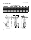
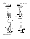
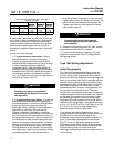
Actuator Mounting
Use the following steps to connect the actuator to a
valve body or other equipment. Unless otherwise
specified, key numbers are shown in figures 12
and 13. Mounting dimensions are shown in figures 4,
5, 6, and 7.
Note
For an actuator with an H mounting
adaptation and a 22.2 through 38.1 mm
(7/8 through 1-1/2 inch) output shaft,
find dimensions and center of gravity
information in figures 3, 4, 5, 6, and 9,