


1051 & 1052 H & J
Instruction Manual
Form 5587
November 2006
13
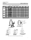
Table 10. Recommended Bolting Torques
(1)
KEY
ACTUATOR SIZE
KEY
NUMBER
40 60 70
NUMBER
NDm lbfDft NDm lbfDft NDm lbfDft
6 27 20 27 20 27 20
7 & 8 41 30 41 30 102 75
9 34 25 102 75 102 75
16 34 25 61 45 102 75
18 81 60 163 120 271 200
21 23 17 68 50 68 50
23 34 25 81 60 81 60
28 81 60 163 120 271 200
34 34 25 81 60 81 60
40 9 7 9 7 9 7
54
handwheel
34 25 34 25 34 25
54
down stop
27 20 66 49 69 51
58 102 75 163 120 163 120
141 41 30 41 30 81 60
1. Exceeding any torque requirements could damage the actuator and impair safe
operation.
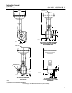
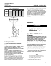
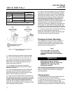
To adjust the spring, insert a round rod into one of
the slots in the lower bearing seat (key 73,
figure 13). Slot diameter is 9.5 mm (3/8-inch) for
size 40 actuators, 15.9 mm (5/8-inch) for size 60
actuators, and 19.1 mm (3/4-inch) for size 70
actuators.
Rotate the bearing seat to move it toward the
casings (keys 1 and 2, figure 13) to increase initial
compression or away from the casings to decrease
initial compression.
Stroking Range
The initial spring set listed on the nameplate has
been determined to be the optimum setting, and it is
not recommended to make spring adjustments that
will cause this value to change or be exceeded. For
push-down-to-open (PDTO) action, the initial spring
set is normally the maximum allowable to provide
the maximum spring closing force. Any increase of
this setting could over-stress the spring at full travel.
For push-down-to-close (PDTC) action, the initial
spring set has been determined to be the optimum
balance between the air to close and the spring to
open breakout torque.
If the Type 1052 actuator is to be changed from one
action to another (i.e., from PDTC to PDTO), first
refer to the initial spring compression values listed in
the table for keys 11 and 13 in the Parts List section.
Then adjust the unit according to the procedures in
the Initial Compression portion of this section.
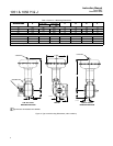
Maintenance
Actuator parts are subject to normal wear and must
be inspected and replaced as necessary. The
frequency of inspection and replacement depends
upon the severity of service conditions. Instructions
are given below for disassembly and assembly of
parts. Key numbers referenced in the following steps
are shown in figure 12 for Type 1051 actuators and
in figure 13 for Type 1052 actuators unless
otherwise specified.
WARNING
Avoid personal injury or property
damage from sudden release of
process pressure or uncontrolled
movement of parts. Before performing
any maintenance operations:
D Always wear protective gloves,
clothing, and eyewear when
performing any maintenance
operations to avoid personal injury.
D Disconnect any operating lines
providing air pressure, electric power,
or a control signal to the actuator. Be
sure the actuator cannot suddenly
open or close the valve.
D Use bypass valves or completely
shut off the process to isolate the
valve from process pressure. Relieve
process pressure from both sides of
the valve. Drain the process media
from both sides of the valve.
D Vent the power actuator loading
pressure and relieve any actuator
spring precompression.
D Use lock-out procedures to be
sure that the above measures stay in
effect while you work on the
equipment.
D The valve packing box may
contain process fluids that are
pressurized, even when the valve has
been removed from the pipeline.
Process fluids may spray out under
pressure when removing the packing
hardware or packing rings, or when
loosening the packing box pipe plug.
D Check with your process or safety
engineer for any additional measures
that must be taken to protect against
process media.