


1051 & 1052 H & J
Instruction Manual
Form 5587
November 2006
11
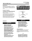
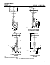
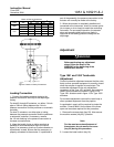
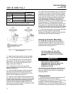
Center of Gravity Dimensions
ACTUATOR ACTUATOR
X Y
ACTUATOR
TYPE
ACTUATOR
SIZE
mm Inch mm Inch
1051
40 15 0.6 191 7.5
1051
60 10 0.4 361 14.2
40 15 0.6 241 9.5
1052
60 10 0.4 432 17.0
1052
70 23 0.9 488 19.2
Figure 9. Center of Gravity Dimensions
Loading Connection
1. Connect the loading pressure piping to the
pressure connection in the top of the diaphragm
casing.
For size 40 through 60 actuators, run either 1/4-inch
pipe or 3/8-inch tubing between the 1/4-inch
pressure connection and the positioner or automatic
controller.
For size 70 actuators, run either pipe or tubing
between the pressure connection and the positioner
or automatic controller. If necessary, remove
the 1/4-inch bushing in the pressure connection to
increase connection size.
2. Keep the length of pipe or tubing as short as
possible to avoid transmission lag in the control
signal. If an accessory (such as a volume booster or
a positioner) is used, be sure that the accessory is
properly connected to the actuator. If a positioner is
part of the assembly, the pressure connection to the
actuator will normally be made at the factory.
3. When the actuator is completely installed and
connected to the instrument, check for correct action
(air-to-open or air-to-close) to match the controlling
instrument. For successful operation, the actuator
stem and operating shaft must move freely in
response to the loading pressure change on the
diaphragm.
Adjustment
WARNING
Before performing any adjustment
steps, follow the steps in the
WARNING at the beginning of the
Maintenance section.
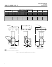
Type 1051 and 1052 Turnbuckle
Adjustment
Correct turnbuckle adjustment ensures that the valve
body or other operated equipment is correctly closed
when the actuator is against its travel stops. The
turnbuckle adjustment is the only adjustment
necessary on the Type 1051 actuator. Key numbers
used in this procedure are shown in figure 12 for
Type 1051 actuators and in figure 13 for Type 1052
actuators.
For accurate adjustment, remove the valve body or
other operated equipment from the pipeline.
A regulated air supply will be required to stroke the
actuator. Consult table 9 for the sizes of the three
open end wrenches required for this procedure.
1. Remove the access plate (key 59). Also remove
the machine screws (key 60), if present.
Note
For the most accurate adjustment of
the actuator, do not remove the cover
(key 33) during this procedure.
2. Loosen the lower locknut (key 16).