


1051 & 1052 H & J
Instruction Manual
Form 5587
November 2006
10
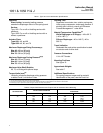
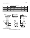
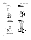
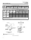
Table 7. Approximate Actuator Weights
SIZE
TYPE 1051 TYPE 1052 TOP-MOUNTED HANDWHEEL
SIZE
Kg Lb Kg Lb Kg Lb
40
60
70
43
89
–––
94
197
–––
45
92
123
99
203
272
7.3
11
21.3
16
24
47
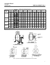
Table 8. Keyway Alignment Information
(1)
DESIRED
DESIRED
ACTUATOR
COUPLING
VALVE SHAFT KEYWAY TO USE FOR FISHTAILR DISC VALVE
BODIES
(2)
(SEE FIGURE 10)
DESIRED
ACTUATOR
ACTION
DESIRED
SHAFT
ROTATION,
ACTUATOR
MOUNTING
POSITION
COUPLING
KEYWAY TO
USE
(
3
)
Clockwise to
Close Valve Action
(4)
Counterclockwise to
Close Valve Action
(4)
ACTION
OO,
DEGREES
POSITION
USE
(3)
Flow Left to
Right
(4)
Flow Right to
Left
(4)
Flow Left to
Right
(4)
Flow Right to
Left
(4)
1 B Nose Tail Tail Nose
Push Down to
60 or 90
2 A Tail Nose Nose Tail
Push
Down
to
Open (PDTO)
60 or 90
3 B Tail Nose Nose Tail
p( )
4 A Nose Tail Tail Nose
1 A Tail Nose Tail Nose
Push Down to
60
(5)
or 90
2 B Tail Nose Tail Nose
Push
Down
to
Close (PDTC)
60
(5)
or 90
3 A Nose Tail Nose Tail
()
4 B Nose Tail Nose Tail
1. For actuators with J mounting.
2. For conventional disc valve bodies, use either valve shaft keyway.
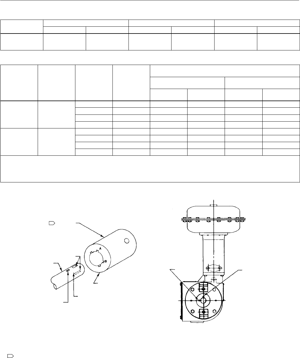
3. See figure 10 for reference coupling orientation to use with this table.
4. When viewed from actuator side of valve body.
5. For 60-degree rotation with PDTC action, the coupling and actuator output shaft assembly will be offset 30 degrees clockwise (for actuator housing construction style B) or
counterclockwise (for actuator housing construction Style A) in the lever when viewed from the splined end of the actuator shaft. 30 degrees is one spline tooth for 9.5, 12.7, and 15.9
mm (3/8, 1/2, and 5/8-inch) valve shafts and two spline teeth for 19.1 through 38.1 mm (3/4 through 1-1/2 inch) valve shafts.
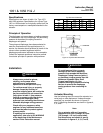
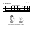
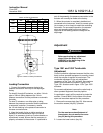
Figure 8. Valve Shaft Coupling
EXPLODED VIEW OF VALVE SHAFT
AND COUPLING
REFERENCE COUPLING ORIENTATION
FOR TABLE 8
NOTE:
FOR USE WITH J MOUNTING ADAPTATION (UP TO 50.8 mm (2-INCH)
KEYED SHAFT DIAMETERS.
1
1
A3253-1
FULL KEYWAY
LOCATED ON
NOSE AND TAIL
SIDE OF VALVE SHAFT
VALVE SHAFT
COUPLING
PARTIAL KEYWAY
FOR DETERMINING
DISC POSITION
USE APPROPRIATE LETTERED
KEYWAY AS INDICATED IN
TABLE 8
USE APPROPRIATE
VALVE SHAFT
KEYWAY AS
INDICATED
IN TABLE 8
KEYWAY A
KEYWAY B
ABOVE
KEYWAY A
19B1465-B