


Page 4 of 44
Catalog #91001, 91003, 91004, 91005, 91007, 91009
Rev. 2/06 - RS/mc
©2006 Edelbrock Corporation
Brochure #63-0282
TK-4 Thermocouple Converter Installation
The TK-4 thermocouple converter unit is required to provide signal conditioning of the thermocouple signals. All eleven thermocouples
installed above are connected to a thermocouple converter. The thermocouple cables provided with the thermocouples are four feet
long. When installing the thermocouple converter unit, make sure it is within reach of all the thermocouple cables. Mount the TK-4
thermocouple converter unit using the four mounting holes in the mounting flanges. The converter unit can be mounted anywhere
within reach on the thermocouples including under the hood. If the unit is mounted under the hood, avoid locations very close to the
exhaust headers to prevent excessive temperatures. Also try to mount the converter unit vertically with the thermocouple connectors
pointing down to prevent water accumulation in the converter unit (The converter unit enclosure is splash proof except for the
thermocouple connectors). If the converter unit is mounted in a protected location such as the interior of the vehicle, then the unit can
be mounted in any orientation. Once the TK-4 thermocouple converter unit and the thermocouples are installed, connect the
thermocouples to the converter unit. The general purpose thermocouples have a male thermocouple connector attached for easy
disconnection and removal. These thermocouples are provided with a four-foot thermocouple extension cable. Connect the female
connector on the extension cable to the thermocouple and the male connector to the TK-4 Thermocouple Converter unit.
Wheel / Shaft Speed Sensors
These sensors are supplied with two rare earth magnets and a sensor pickup and can be used to measure either wheel speed or shaft
speeds. The two magnets are mounted equally spaced around the rotating object (wheel or shaft) and the pickup is mounted on a
stationary object. For proper operation, the magnets must pass within a maximum of 1/4 inch of the pickup. Because of this
restriction, it is very important to mount the pickup on something that moves very little relative to the magnets.
For example, if the magnets are mounted on the drive shaft, they should be either mounted close to the transmission end or close to
the rear end and the pickup should be mounted directly to the transmission or the rear end respectively. Similarly, if the magnets are
mounted to a wheel, the pickup must be mounted to a suspension piece that moves with the wheel. The magnets can be either
epoxied in place or taped in place with duct tape.
NOTE: As supplied by the factory, these sensors are configured to measure RPM as they are typically used to measure
input shaft and output shaft RPM. If one of these sensors is used to measure vehicle speed, the sensor must be
calibrated accordingly. The calibration of the speed sensor is unique to each installation. (Refer to the
Sensor
Calibration
section.)
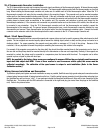
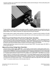
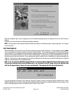
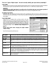
Wiring Harness Installation and Connection
To provide a splash-proof system and make installation as easy as possible, QwikData uses high-grade waterproof connectors and an
external wiring harness instead of having terminals on the box. Push the wiring harness connector(s) onto the mating male plug(s) on
the QwikData box until you hear a “click”. If your package included the Advanced QwikData unit, there will be two connectors on the
QwikData box. The harness with the DB9 connector is connected to the right hand plug (as viewed from the plugs on the QwikData
unit). Refer to the pictures below.