


Page 15 of 44
Catalog #91001, 91003, 91004, 91005, 91007, 91009
Rev. 2/06 - RS/mc
©2006 Edelbrock Corporation
Brochure #63-0282
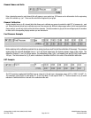
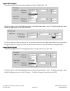
Injector On Time Example
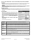
Instead of Duty Cycle, you may want to measure the absolute on or off time of the injectors in milliseconds for each firing cycle. Select
“On Time” or “Off Time” for the input type. Ensure that the maximum length of time of the signal is within the pre-set limits of the
system,
See “Advanced Options”
. The default setting allows you to measure pulse widths of up to 210.5 ms. This is well within the
range of most injector pulses which are usually in the 1 to 30 ms range. So for this example, the calibration numbers can be (0), (0),
and (30), (30).
Note: (We could use any number up to 210.5). The third element is (0), (0) which indicates to QwikData that this is
the end of the calibration table data.
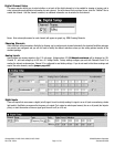
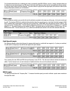
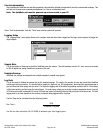
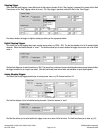
Lap Beacon Example
A lap beacon is an example of a digital input that is configured as a counter. Another example may be an Integrating Flowmeter where
each revolution of the turbine in the flowmeter produces a pulse and each pulse corresponds to a set amount of fuel. So by counting
pulses, you may determine the absolute amount of fuel that has passed. (Note: In most cases for racing applications, we are
interested in the fueling rate (gpm) and thus read flowmeters as microseconds QwikData can measure frequencies of up to 6000 Hz,
but the minimum rises to 202 Hz.
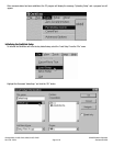
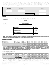
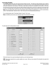
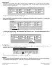
Channel Enable
For each channel that you intend to use, click the “Channel” Box to enable that channel. Until the channel is enabled, no additional
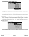
information can be entered for that channel. Channels 9 and 10 are the built-in accelerometers.
These two channels are always enabled as accelerometers unless the Accelerometer Enable boxes on the right side of the form are
de-selected and two jumpers are changed as shown on the
jumper table
.