


Page 3 of 44
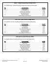
Catalog #91001, 91003, 91004, 91005, 91007, 91009
Rev. 2/06 - RS/mc
©2006 Edelbrock Corporation
Brochure #63-0282
Installation of the QwikData Data Logger Unit:
Important Notice: When installing data log unit avoid RF and or EMI signal interference and make sure all grounds are connected
directly to the negative side of the battery. Keep sensor wiring away from ignition wires. Try to keep all data log unit wiring as far as
possible from CD boxes and wiring. Do not mount the data log next to ignition box or ignition coils. You will want as much distance
between the data log and these devices as possible. Thermocouples and thermocouple extension must also be kept away from ignition
wires, ignition box and coils. If wires have to cross, try to have them cross at a right angle. Avoid paralleling Data log wires with any
ignition wiring (Primary or Secondary).
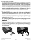
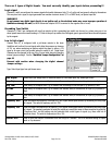
As the QwikData accelerometers are mounted inside the data logger unit, the unit must be mounted in a particular orientation to obtain
accurate acceleration data. The unit must be mounted approximately level and horizontal with the QwikData logo parallel to the
centerline of the car. If possible, the box should be mounted along the centerline at the center of gravity of the car. Mounting in the
cockpit in front of the shifter is often a convenient location. Mounting QwikData with the connectors facing the front of the car will
display left turns and longitudinal acceleration as positive numbers (right turns and braking are displayed as negative numbers). Don't
be overly concerned if you cannot meet these criteria as the measurement errors induced are not great and in general you should be
more concerned with relative acceleration figures, not the absolute numbers. Although not required, some sort of vibration isolation
is usually desirable to prevent noisy accelerometer readings due to vibration. Mount using high-density foam rubber under mounting
screws. Velcro tape is also a good alternative as it allows the box to be easily removed and provides some vibration dampening.
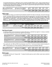
Pressure Sensors
Five pressure sensors are available in pressure ranges:
1 (-15) Vacuum Transducer
2 0-15 psi pressure sensors (Fuel pump) etc.
3 0 - 100 psi pressure sensors (Oil) etc.
4 0-500 psi pressure sensor (Trans Pressure) etc.
5 0-2500 psi pressure sensor (Brakes or Nitrous) etc.
The sensors are provided with a male 1/8 NPT fitting that is compatible with most vehicles (pipe adapters can be used if a different
thread size is needed). Note: Pressure sensors should not be mounted directly to the engine, as excessive vibration can destroy the
sensors. Mount the sensors remotely with an aluminum block, and connect to the engine with small, flexible tubing.
Temperature Sensors
The temperature sensors provided in some QwikData packages are high quality thermocouple devices. Three thermocouples are
provided to measure temperatures such as oil temperature and coolant temperature. These thermocouples are provided with 1/8 NPT
compression fittings that can easily be installed in a similarly threaded hole. To install these thermocouples, thread the compression
fitting into the hole and tighten the base of the fitting (not the compression nut) to prevent leaks. Insert the thermocouple into the hole
and then tighten the compression nut until the thermocouple is secured in place. Connect a thermocouple couple extension cable to
each thermocouple temperature sensor.
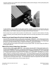
Exhaust Gas Temperature Sensors
The exhaust gas temperature (EGT) thermocouples are typically mounted in each of the exhaust header pipes close to the header
flange (usually about 3" away). The exact location is not critical but you should try to mount all the EGTs at approximately the same
location in each header for consistent measurements. The EGT thermocouples are supplied with a compression fitting similar to the
general purpose thermocouples. The compression fitting consists of four parts; a bung, an adapter, a ferrule, and a compression nut.
To install the EGT thermocouples, you need to drill a 9/16” clearance hole in the exhaust header and then weld the bung into the
header.
NOTE: The bung is threaded with a 1/8” NPT and MUST be mounted with the inside taper facing out.
Once the bung has been welded in place, thread the adapter into the bung and tighten. Place the ferrule into the adapter and loosely
thread the compression nut onto the adapter. Insert the EGT thermocouple into the compression fitting and tighten the compression
nut to secure the thermocouple. Insert the EGT thermocouple into the compression fitting until the tip is approximately in the center
of the header. Secure by tightening the compression nut.