


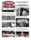
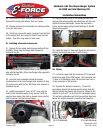
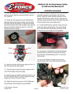
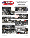

80. Locate the electrical connector on the main harness
previously occupied by the alternator control wiring
harness. Attach the round alternator connector on the
supplied TPS/Alternator harness into this connector and
route the harness around the back of the engine bay, then
forward along the driver side cylinder head.
81. Locate the MAF sensor connector on the driver side
of the main engine wiring harness. Use a pick shaped
tool to hook the center tab provision on the face of the
connector and pry the wedge lock out altogether.
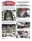
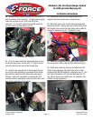
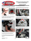
82. Use a razor or sharp knife to cut the electrical tape
directly behind the connector, then pull the connector
away from the convoluted tubing until 2” of wire have
been exposed.
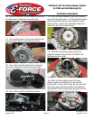
83. Use a small needle or safety pin to de-pin and
remove the two wires on the right side (gray and gray
with a red stripe).
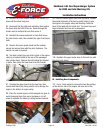
74. Once the wedge lock is elevated, de-pin all four wires
on the connector using the same procedure as with the
ETC connector.
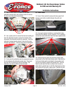
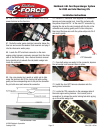
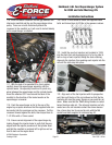
75. Detach the TPS connector from the TPS/Alternator
extension harness and raise the wedge lock by pushing
the center lock tab and pulling up. Align the slot on the
wire terminal with the tab in the connector, then insert the
yellow wire with the white stripe into Pin 1 of the TPS
Connector and seat it gently.
TPS Connector
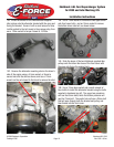
76. Insert the red wire with the green stripe into Pin 2 of
the TPS Connector and seat it gently.
77. Insert the black wire with the green stripe into Pin 3
of the TPS Connector and seat it gently.
78. Insert the grey wire with the white stripe into Pin 4 of
the TPS Connector and seat it gently. Depress the white
wedge lock to secure the wires in place.
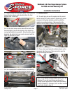
79. Attach the electrical connector of the TPS/Alternator
wiring harness to the connector you just installed.
©2009 Edelbrock Corporation
Catalog #1580
Brochure #63-1580
Rev. 2/09 - AJ/mc
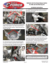
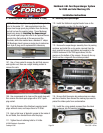
Edelbrock 4.6L Ford Supercharger System
for 2005 and later Mustang GTs
Installation Instructions
Page 16
Pin #4
Pin #1
Pin #3
Pin #2