


© 2003 directed electronics, inc.
21
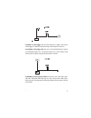
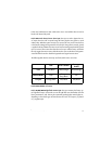
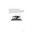
door lock harness wire connection guide
___
___
___
The control module can control 2 common power door lock types without any addition-
al parts. With certain verhicles, or if an actuator is to be installed, either a 451M Door
Lock Relay Satellite or two relays will be required. Refer to TechTips document 1041.
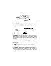
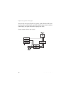
plug-in harnesses
integrated LED/Valet
®
switch
The integrated LED/Valet
®
switch should be accessible from the driver’s seat. The
Valet
®
part of the integrated LED/Valet
®
switch plugs into the blue port on the side of
the unit. Check for rear clearance before drilling a 5/16-inch hole and mounting the
switch. The LED part of the integrated LED/Valet
®
switch operates at 2V DC and plugs
into the white port on the side of the unit. Make sure the LED wires are not shorted to
ground as the LED will be damaged.
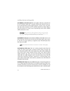
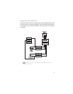
data port—Bitwriter
®
The black three-pin port can be used for programming the unit or to accommodate a
serial controller. The Bitwriter
®
is recommended for programming.
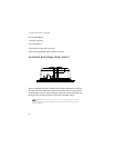
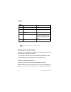
BLUE (-) Unlock, (+) Lock Output
Not Used
GREEN (-) Lock, (+) Unlock Output
H3/A
H3/B
H3/C