


14
© 2003 directed electronics, inc.
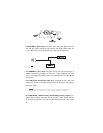
H1/9 YELLOW (+) ignition input: Connect this wire to the (+)12V ignition wire. This
wire must show (+)12V with the key in Run position and during cranking. Take care
to insure that this wire cannot be shorted to the vehicle chassis at any point.
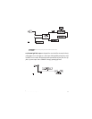
H1/10 BROWN (+) siren output: This output can be used if an optional siren is
installed. Connect this to the RED wire of the siren. Connect the BLACK wire of the
siren to (-) chassis gound, preferably at the same point as the control module’s BLACK
ground wire.
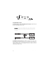
H1/11 RED (+)12V constant power input: Before connecting this wire, remove the
supplied fuse. Connect to the battery positive terminal or the constant 12V supply to
the ignition switch.
NNOOTTEE::
Always use a fuse within 12 inches of the point you obtain (+)12V. Do not use
the 15A fuse in the harness for this purpose. This fuse protects the module itself.
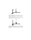
H1/12 RED/WHITE (-) 200mA auxiliary channel/delayed accessory output: If pro-
grammed for an auxiliary output, this wire will provide a (-) pulse when the lock but-
ton on the factory transmitter is pressed twice within three seconds. This output can be