


10
© 2003 directed electronics, inc.
main harness wire connection guide
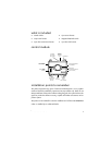
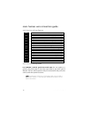
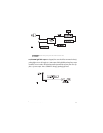
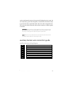
main harness wiring diagram
___
___
___
___
___
___
___
___
___
___
___
___
main harness wiring guide
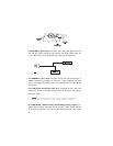
H1/1 ORANGE (-) 500 mA ground-when-armed output: This wire supplies a (-)
ground as long as the system is armed. This output ceases as soon as the system is
disarmed. This wire controls operation of the pre-wired starter kill relay and can be
used to control other optional accessories.
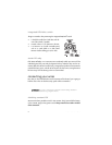
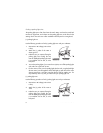
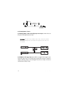
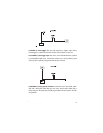
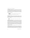
NNOOTTEE::
If connecting the orange wire to control another module, such as a 529T or
530T window controller, a 1 amp diode (type 1N4004) will be required. Insert the
diode as shown below.
RED/WHITE (-) 200mA Auxiliary Channel/Delayed Accessory Output
RED (+) 12V Constant Power Input
BROWN (+) Siren Output
YELLOW (+) Ignition Input
BLACK (-) Chassis Ground Input
VIOLET (+) Door Trigger Input
BLUE (-) Instant Trigger (Hood and Trunk Pin)
GREEN (-) Door Trigger Input
BLACK/WHITE (-) 200mA Domelight Supervision Output
WHITE/BLUE No Function
WHITE (+)/(-) Light Flash Output
ORANGE (-) 500mA Ground When Armed
H1/1
H1/2
H1/3
H1/4
H1/5
H1/6
H1/7
H1/8
H1/9
H1/10
H1/11
H1/12