


© 2003 directed electronics, inc.
15
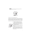
used to control optional accessories. If programmed for delayed accessory output, this
wire will provide (-) ground when the ignition is turned off and will continue to output
(-) ground until a door is opened then closed. This can be used to energize the acces-
sory circuit in the vehicle to keep the radio and other accessories on after the ignition
is turned off.
IIMMPPOORRTTAANNTT!!
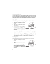
Never use this wire to drive anything but a relay or a low-current input!
This transistorized output can only supply (-) 200 mA, and connecting directly to a sole-
noid, motor, or other high-current device will cause the module to fail.
NNOOTTEE::
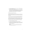
Zones 2 and 4 are shunted when this channel becomes active. Zones 2 and
4 reactivate 5-seconds after this channel’s output ceases.
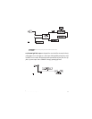
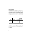
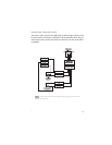
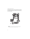
auxiliary harness wire connection guide
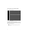
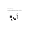
auxiliary harness wiring diagram
___
___
___
___
___
___
___
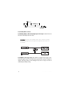
YELLOW/BLACK Light Flash Monitor Input
VIOLET/BLACK No Function
GRAY (+) Trunk Release/Sensor Shunt Input
BLUE Disarm Input
RED Disarm Defeat Input
GREEN Arm Input
BROWN (-) Horn Honk Output
H2/1
H2/2
H2/3
H2/4
H2/5
H2/6
H2/7