


21
© 2004 Directed Electronics, Inc.
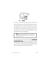
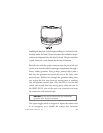
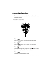
Engine monitoring (tachometer—optional)
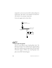
Identify the suspect wire according to the web information.
Place the black lead of the multi-meter on the negative battery
post and secure it. Put the multi-meter in the AC position and
connect the probe to the suspect wire with the red lead of the
multi-meter. Then start the vehicle with the key. With the
engine at idle the multi-meter should read between .05 volts to
1.5 volts.
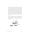
Have a second person press the gas pedal to increase the RPMs
and watch the meter display. When the RPMs increase the
voltage should read between 1.5 volts and 2.9 volts. Once the
correct tachometer wire has been identified, turn the vehicle off.
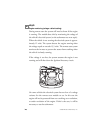
Run the VIOLET/WHITE (H1/2) wire from the main
connector through the firewall into the engine compartment
along side the hood pin wire. Use the same procedure as with the
note! In the following procedure do NOT use the LED
tester. Use of this tester can cause grounding of sensitive
electrical components causing damage, including damage
to the power train control module.
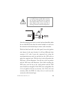
warning! In the following procedure do
not wear loose clothing that could get
entangled in rotating engine components.
Ensure that your hands and arms are well
clear of these rotating components when
working in the engine compartment.
Lastly, ensure that all wires and tools are
clear of falling into or entanglement with
these rotating components.