


11
© 2004 Directed Electronics, Inc.
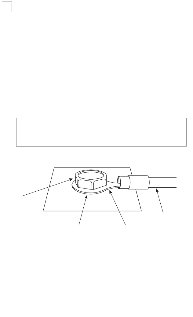
step 1
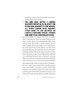
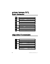
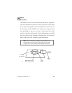
Ground Wire
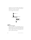
The BLACK (H1/5) wire on the main 8-pin harness is ground.
This wire should be connected to a clean, paint-free area of metal
in the drivers kick panel area. First strip back a ¾-inch section of
the insulation off the BLACK wire and crimp a ring terminal
(not provided) to that wire. Locate a clean, paint-free metal
surface in the drivers kick panel. Using a self-tapping screw, drill
the screw with the ring terminal to the metal area. Once screwed
down, pull on the wire to ensure a good connection.
SELF-TAPPING
BOLT OR SCREW
RING
TERMINAL
GROUND
WIRE
NOTE: REMOVE ANY PAINT
BELOW RING CONNECTOR
DIA-591
note: More problems are attributed to poor ground con-
nections than any other cause. Take extra care to ensure
the ground is a clean metal-to-metal contact and secure.
➜